

Standalone bus bar kit system
a kit system and bus bar technology, applied in the field of stand-alone bus bar kit systems, can solve the problems of no power back up and unsatisfactory solutions, and achieve the effects of convenient and reliable use, convenient and convenient use, and convenient us
- Summary
- Abstract
- Description
- Claims
- Application Information
AI Technical Summary
Benefits of technology
Problems solved by technology
Method used
Image

Examples
Embodiment Construction
[0021] When referring to the preferred embodiment, certain terminology will be utilized for the sake of clarity. Use of such terminology is intended to encompass not only the described embodiment, but also technical equivalents, which operate and function in substantially the same way to bring about the same result.
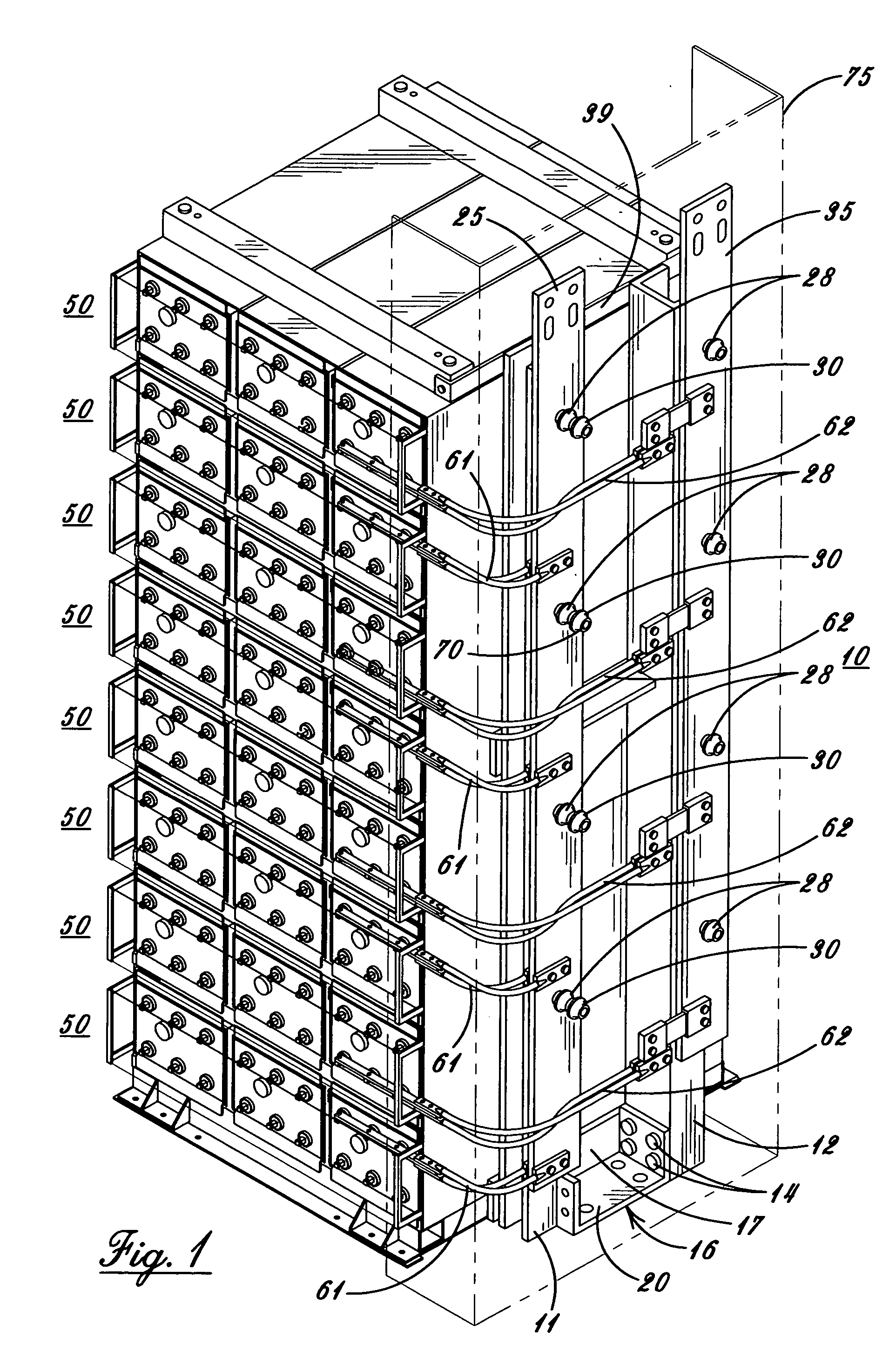
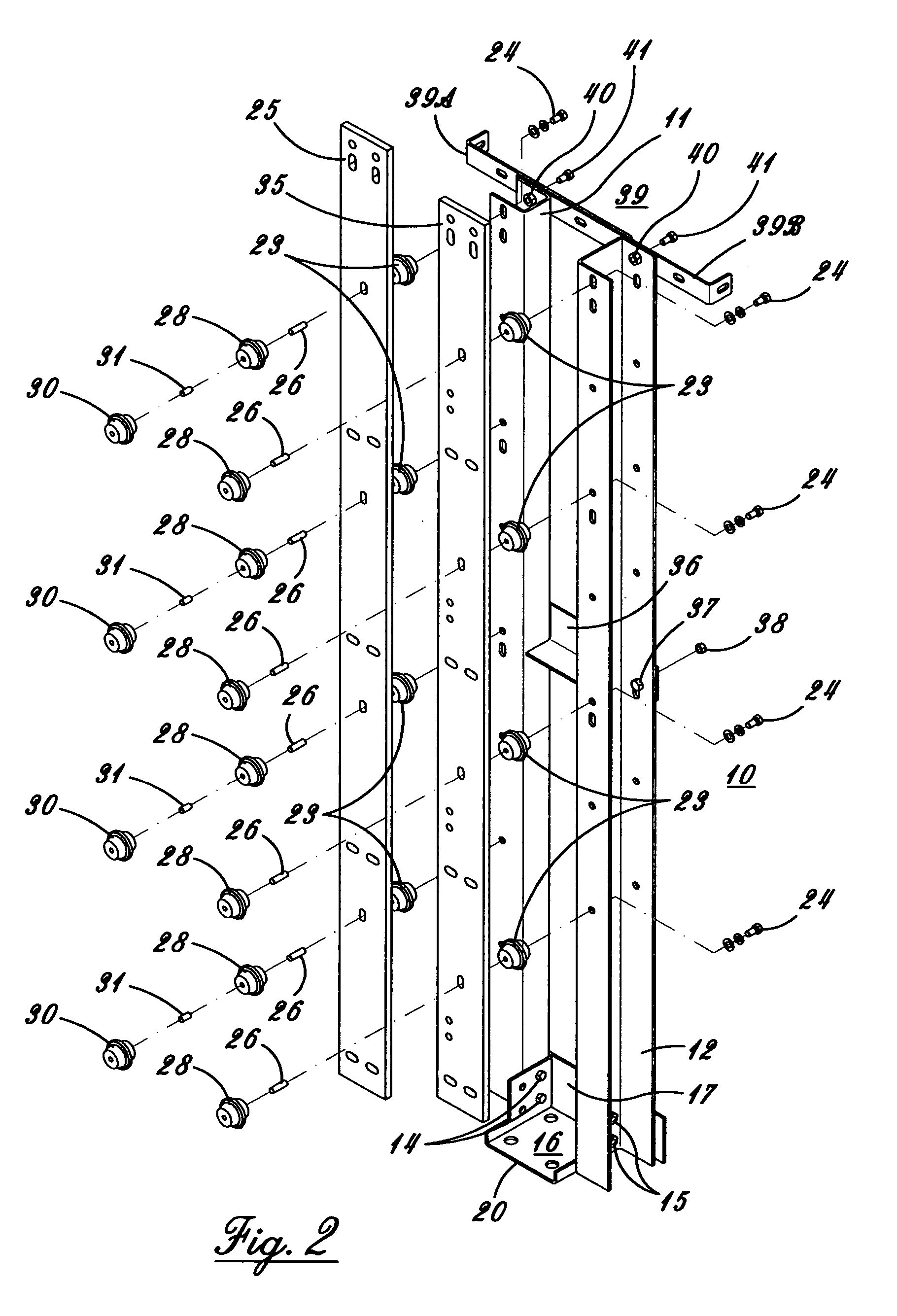
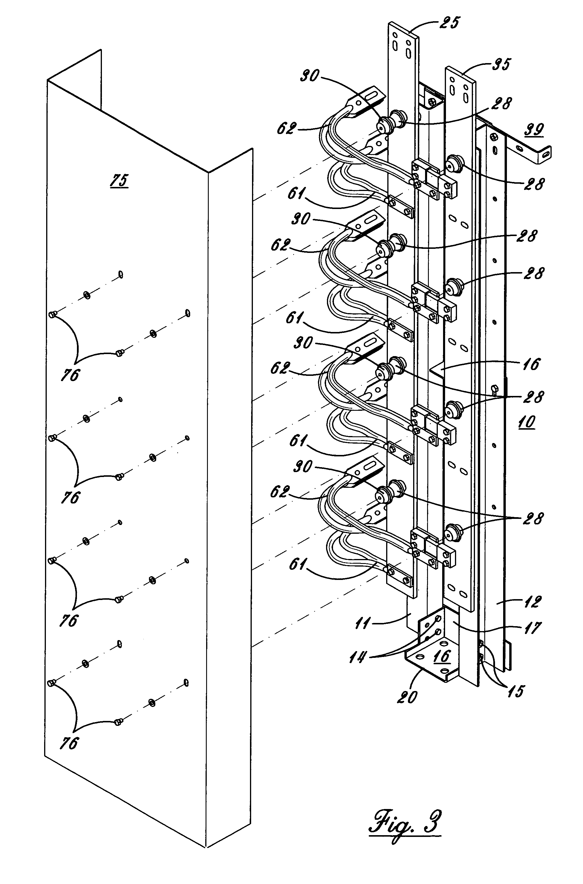
[0022] Preferring now more particularly to the drawings and FIGS. 1-3 thereof the standalone bus bar kit system 10 is therein illustrated. The system 10 includes a pair of uprights 11 and 12, which are U shaped and mounted by bolts 14 and nuts 15 to a floor mounting base 16. The base 16 is preferably constructed from a single piece of metal, preferably of steel, with a back plate 17, and a bottom plate 20 for mounting to a floor (not shown). The upright 11 has a plurality of spaced glastic insulators 23, of well known type, mounted thereto by bolts 24 extending through the upright 11 into insulators 23. A positive bus bar 25 is mounted to insulators 23 by studs 26 extend...
PUM
| Property | Measurement | Unit |
|---|---|---|
| electric power | aaaaa | aaaaa |
| power | aaaaa | aaaaa |
| flexibility | aaaaa | aaaaa |
Abstract
Description
Claims
Application Information