Back light unit and method of adjusting spectral distribution thereof

a back light and spectral distribution technology, applied in the field of back light units, can solve the problems of low efficiency, low cost and low efficiency of methods, and ineffective adjustment of white ligh

Inactive Publication Date: 2007-01-25
INNOLUX CORP +1
View PDF5 Cites 54 Cited by
  • Summary
  • Abstract
  • Description
  • Claims
  • Application Information

AI Technical Summary

Benefits of technology

[0011] It is an advantage of the technology of color LED light sources with single LED chip is fully developed so that it may be used to effectively adjust the white light having small spectral

Problems solved by technology

However, comparing to the lighting equipments which are currently popular, such as incandescent tungsten lamps and fluorescent lamps, the technology of white LED is not mature yet for that the white LED light is more costly and less efficient.
Furthermore, it also has the disadvantage of smaller spectral distribution.
This method has low cost and low efficiency wherein it is widely used by the industry.
However, the problem is that the white light produced with this method may have insufficient intensities of the red light between 600 to 700 nanometers (nm) and of the green light between 480 to 580 nm.
The insufficiency of the red light is en

Method used


Image

  • Back light unit and method of adjusting spectral distribution thereof
  • Back light unit and method of adjusting spectral distribution thereof
  • Back light unit and method of adjusting spectral distribution thereof

Examples


first embodiment

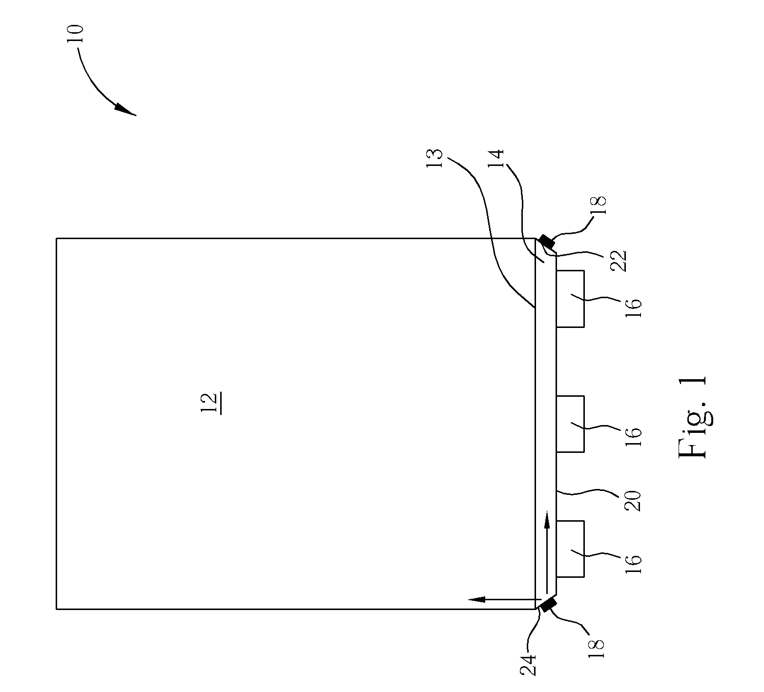
[0018] Please refer to FIG. 1. FIG. 1 is a schematic diagram of a back light unit 10 according to the in this invention. The back light unit 10 comprises a light guide plate 12, a light guide bar 14 on one side of the light guide plate, three white LED light sources 16 on the side of the light guide bar 14 opposite to the side connecting to the light guide plate 12, and two color LED light sources 18. As shown in FIG. 1, the light guide plate 12 is a flat or wedge-shaped plate. One side of the light guide plate 12 is an incidence face 13 of the light guide plate 12. A light guide bar 14 is set on this incidence face 13 and connects to the light guide plate 12. The light guide bar 14 and the light guide plate 12 may be a monolithic structure or be made of same materials. The first light-incidence face 20 of the light guide bar 14 is positioned at the surface opposite to the incidence face 13 of the light guide plate 12. Two sides of the light guide bar 14 are two nicks, and the secon...

second embodiment

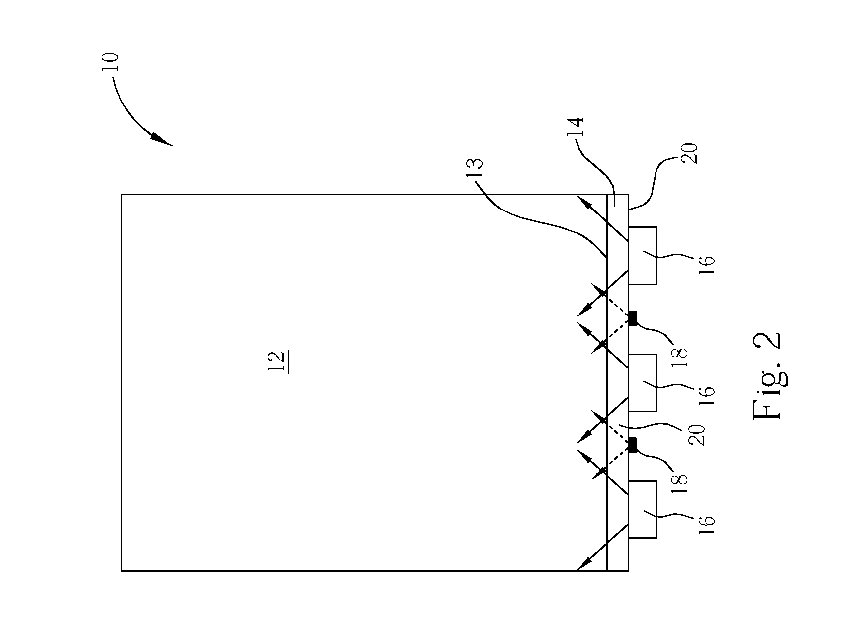
[0020] Please refer to FIG. 2. FIG. 2 shows the back light unit according to the present invention. The symbols of each part here are the same as in the previous embodiment. In this embodiment, the color LED light sources 18 are set between each two nearby white LED light sources 16 and on the surface of the first light-incidence face 20. Therefore, the light produced by the white LED light sources 16 and the color LED light sources 18 will be mixed completely in the light guide bar 14, and provide white light with preferable color saturation to the light guide plate 12. The arrows with solid lines in FIG. 2 indicate the light produced by the white LED light sources 16, and the arrows with dashed lines indicate the light produced by the color LED light sources 18.

[0021] In the above-mentioned first and second embodiments, a white LED light source 16 comprises a single blue chip with phosphor. The light produced by these light sources lacks the light with red wavelength. Therefore, t...

third embodiment

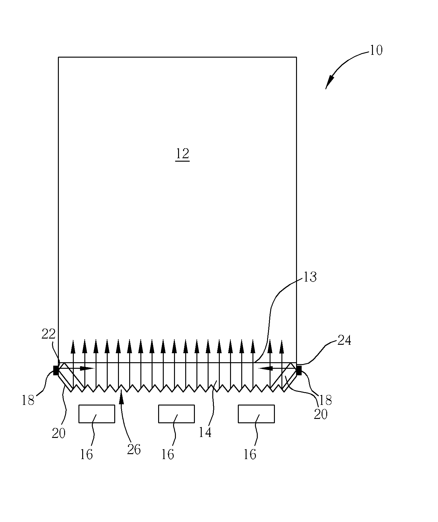
[0023] Please refer to FIG. 3. FIG. 3 shows the back light unit of the present invention. All symbols used for parts here are the same as in previous embodiments. In this embodiment, the first light-incidence face 20 of the light guide bar 14 further comprises a plurality of V-cuts 26 or has been roughened. As a result, the light from the color LED light sources 18 on the second and third light-incidence faces 22, 24 may be transmitted to the center of the light guide bar 14. Also, due to the differences between the refraction in the air and the refraction in the light guide bar 14, the V-cuts 26 or rough edges of the light guide bar 14 may serve as a prism structure that creates a prism effects and reflect the light to the light guide plate 12 through its incidence face 13 (the light-exit face of the light guide bar 14), as the arrows show in FIG. 3.

[0024] Please refer to FIG. 4. FIG. 4 is a schematic diagram of the forth embodiment of the present invention. The back light unit 50 ...


PUM


Abstract

A back light unit having a light guide plate, a light guide bar connecting to the light guide plate, at least a white LED light source, and at least a color LED light source. Each of the LED light sources is positioned at a side of the light guide bar. The color LED light source compensates white light from the white LED light source that cannot produce preferable white light. Accordingly, the back light unit can produce white light that provides preferable color saturation to a display in cooperation of the white LED light source and the color LED light source.

Description

BACKGROUND OF THE INVENTION [0001] 1. Field of the Invention [0002] The invention relates to a back light unit, and more particularly, to a back light unit using light emitting diodes (LEDs) as its back light source. [0003] 2. Description of the Prior Art [0004] A light emitting diode (LED) is a new type of small light sources. It has advantages of long life, small size, high shock resistance, and low power consumption. As a result, LEDs have been widely used as the indicator lights or light sources of electronic appliances and machines. Recently, due to the development of the colorfulness and brightness of LEDs, they had been applied to mobile electronics as the back light sources of the mid- or small-size displays, especially for the small color liquid crystal displays (LCD). [0005] Because white lights are used as the major back light source for the LCD displays of most information electronic products, the LEDs used in the back light units must be able to produce white lights. Ho...

Claims


Application Information

Patent Timeline
IPC IPC(8): F21V7/04
CPCG02B6/0016G02B6/0068G02B6/0046G02B6/0028
Inventor YU, CHUAN-PEIWANG, MAO-JUNG
Owner INNOLUX CORP
Why Eureka
Try Eureka