Active steering for marine seismic sources

a technology of active steering and seismic sources, applied in the field of seismic exploration, can solve the problems of limiting the ability to position source equipment and receivers in different relative positions and orientations, diverters will not maintain the desired streamer position, and this, of course, has been impossible in a marine survey, so as to avoid obstruction in or under the water

Active Publication Date: 2007-01-25
REFLECTION MARINE NORGE AS
View PDF87 Cites 50 Cited by
  • Summary
  • Abstract
  • Description
  • Claims
  • Application Information

AI Technical Summary

Benefits of technology

[0019] The method of the present invention further provides a method for avoiding obstruction in or under the water. These steps include detecting acoustic signals or reflections indicating obstructions in the path of the source array and adjusting the deflector device to steer around an obstruction detected by the acoustical transducer and receiver.

Problems solved by technology

If forward motion changes due to ocean currents and other environmental factors, the diverters will not maintain the desired streamer position.
This, of course, has been impossible to accomplish in a marine survey because the acoustical source arrays are typically towed behind the tow vessel and are subject to wave and current movement.
In addition to the deployment and operation difficulties associated with towing multiple streamers, conventional techniques limit the ability to position source equipment and receivers in different relative positions and orientations.
Because the sources and receivers are towed behind the same seismic vessel, array design is limited by the tow configuration.
Each towed array is also subject to crosscurrents, wind, waves, shallow water, and navigation obstacles that limit the coverage provided by the survey system.
These attempts have not provided optimal control of the location of the source arrays under towing conditions.
Furthermore, the distance ropes create a significant drag that must be overcome by the tow vessel and that places a great deal of tension on the towing cables and attachments.

Method used


Image

  • Active steering for marine seismic sources
  • Active steering for marine seismic sources
  • Active steering for marine seismic sources

Examples


Embodiment Construction

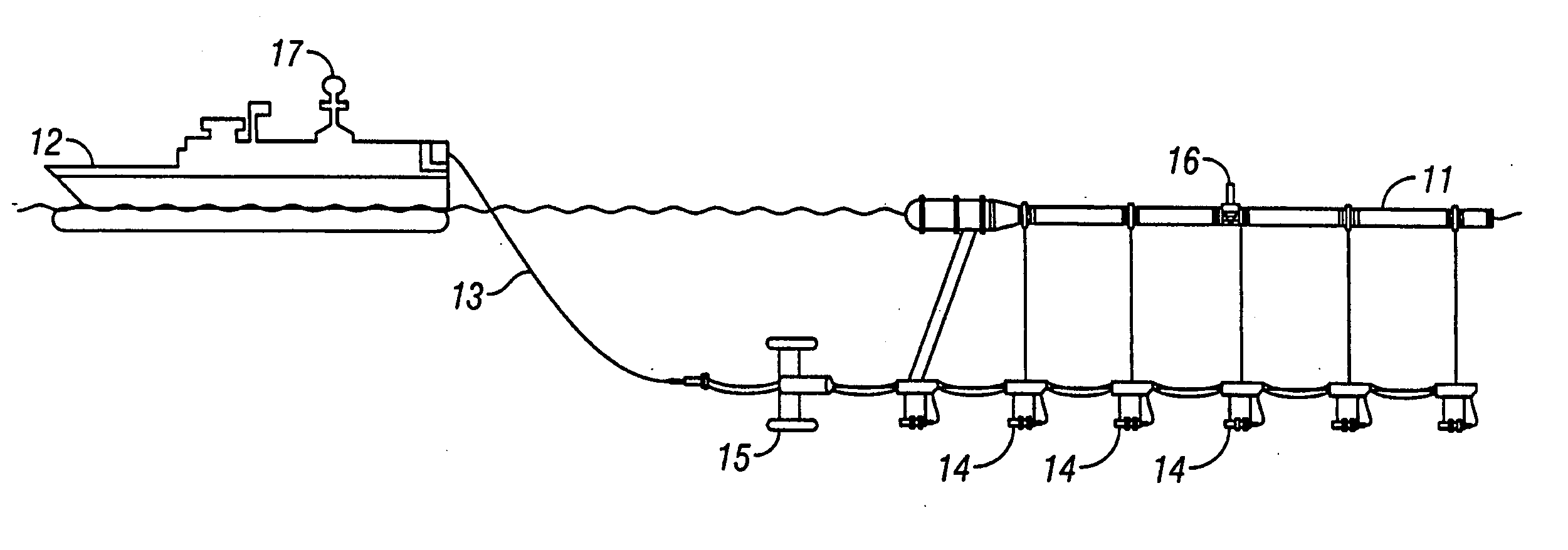
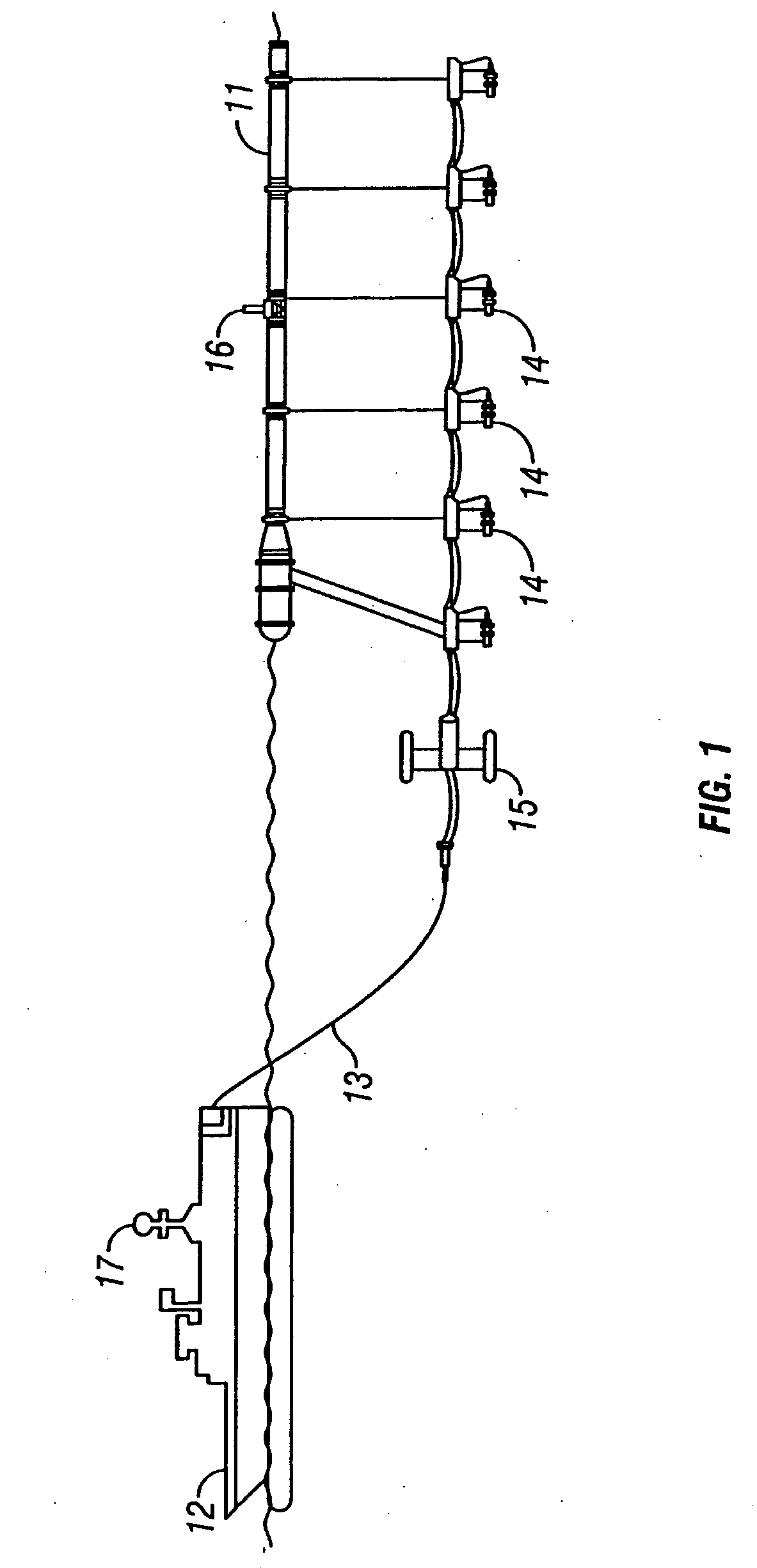
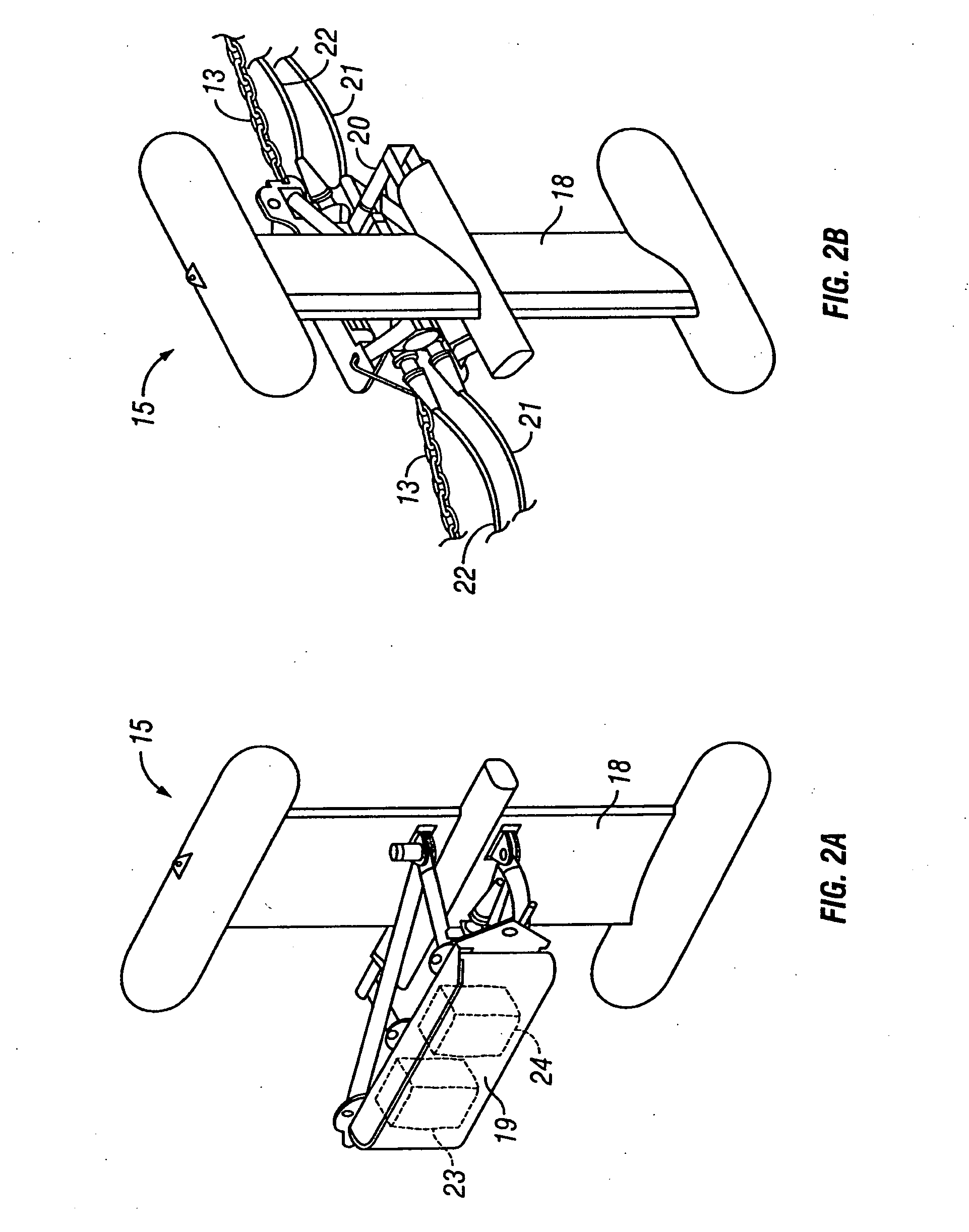
[0035] The present invention provides a seismic survey system that includes one or more source arrays towed behind a tow vessel. The system may be used for conducting seismic surveys of the subsurface geological formations that underlie a body of water. The system comprises a source array and an independently steerable deflector device that is coupled to the source array, preferably suspended from a float element of the source array or alternatively, from a separate independent float. The deflector device controls the position of the source array by exerting a lateral force against the source array as the deflector device is towed through the water. The deflector device preferably includes one wing that may be angularly adjusted to steer the source array to a desired position behind the tow vessel.

[0036] The deflector device is a hydrodynamic body that uses the water velocity, achieved by being towed by the tow vessel through the water, to generate a lateral force to steer the sour...


PUM


Abstract

A seismic survey system having a source array (11) coupled to a deflector device (15) that controls the position of the source array. A positioning system unit (16) is mounted on the source array to provide a signal to a controller, informing the controller of the current position of the source array so that the controller can control the position of the deflector device (15) and the coupled source array. A seismic source (14) on the source array may be triggered when the source array is at a desired location as measured by the positioning system unit. The deflector device (15) comprises one or more wings (18) in a generally vertical or, alternatively, in a generally horizontal arrangement disposed adjacent to a central body (19). The streamlined central body has connection points that allow the deflector device (15) to be connected to a tow cable (13) from the tow vessel (12) and to the source array (11).

Description

BACKGROUND OF THE INVENTION [0001] 1. Field of the Invention[0002] This invention relates to seismic exploration and more specifically, to marine seismic survey systems. [0003] 1. Description of the Related Art [0004] Marine seismic exploration investigates and maps the structure and character of subsurface geological formations underlying a body of water. For large survey areas, seismic vessels tow one or more seismic sources and multiple seismic streamer cables through the water. The seismic sources typically comprise compressed air guns for generating acoustic pulses in the water. The energy from these pulses propagates downwardly into the geological formations and is reflected upwardly from the interfaces between subsurface geological formations. The reflected energy is sensed with hydrophones attached to the seismic streamers, and data representing such energy is recorded and processed to provide information about the underlying geological features. [0005] Three-dimensional (3-...

Claims


Application Information

Patent Timeline
Patent Type & Authority Applications(United States)
IPC IPC(8): G01V1/38
CPCG01V1/3826G01V1/3817G01V1/3835B63B21/66
Inventor HOWLID, MARTINSINGH, ROHITASHVA
Owner REFLECTION MARINE NORGE AS
Why Eureka
Try Eureka