
In-band rate indicator methods and apparatus

a technology of in-band rate and indicator method, applied in the field of methods and apparatus for indicating data rate option information, can solve problems such as undesirable increase in overhead

Inactive Publication Date: 2007-01-25
QUALCOMM INC
View PDF35 Cites 24 Cited by
  • Summary
  • Abstract
  • Description
  • Claims
  • Application Information

AI Technical Summary

Benefits of technology

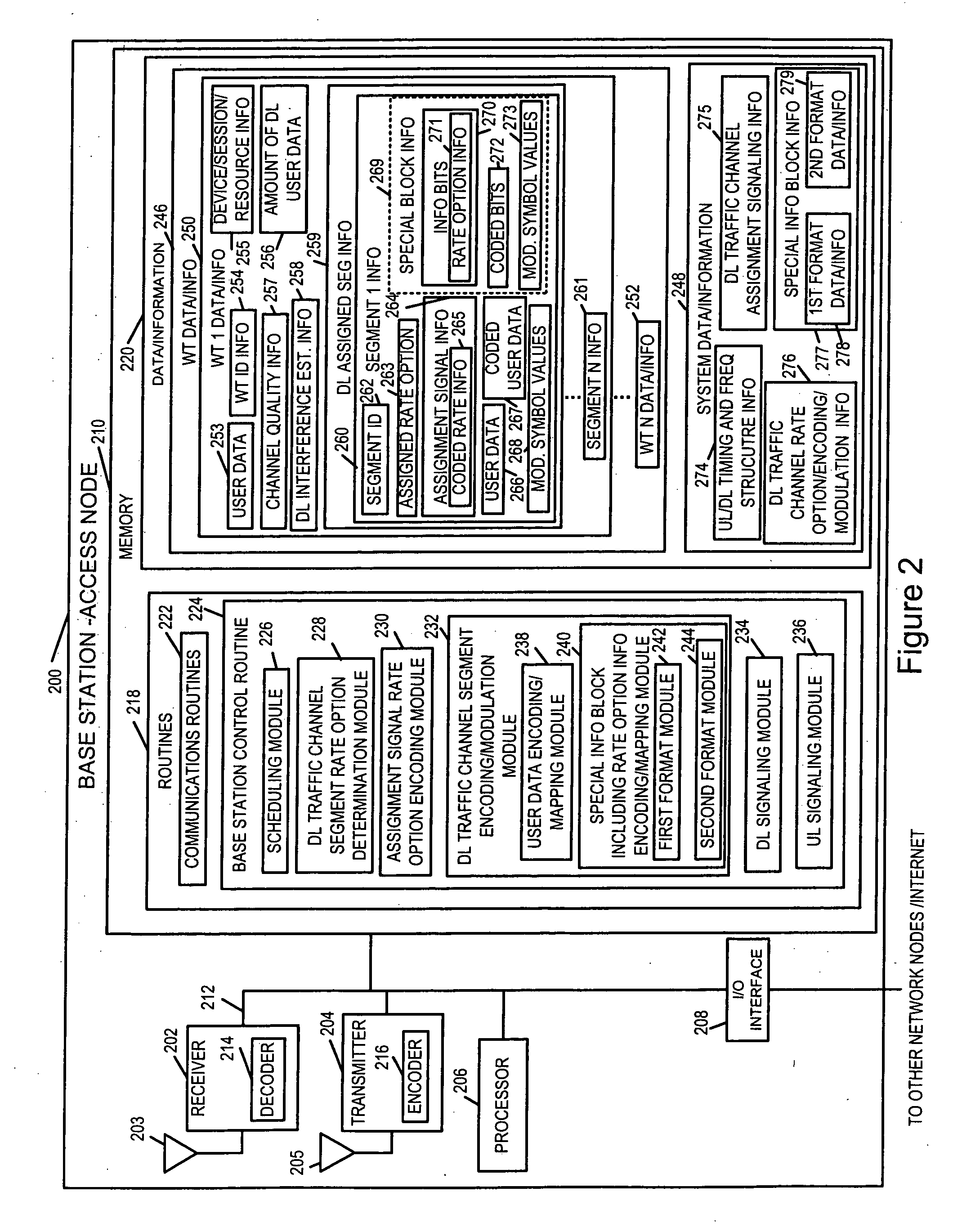
[0017] In accordance with a feature of various embodiments of the present invention, the base station does not specifically identify the format type of the special information block, but rather the grouping of codes allows a wireless terminal receiving the special information block to distinguish and identify the format type of received special information block. In some implementations, the wireless terminal, after having determined the format type of the special information block, will attempt to recover the information bit or bits of special information block which identify the data rate option used for the downlink traffic channel segment. Using a recovered data rate option value, the wireless terminal can properly interpret the received modulation symbol values corresponding to the coded user data, and attempt to recover the user data information bits which were encoded by the base station prior to transmission.

Problems solved by technology

However, as the number of supported data rate options increases, the number of bits required to be dedicated in the assignment signal to uniquely indicate the assigned rate option increases, representing an undesirable increase in overhead.

Method used


Image

  • In-band rate indicator methods and apparatus
  • In-band rate indicator methods and apparatus
  • In-band rate indicator methods and apparatus

Examples


Embodiment Construction

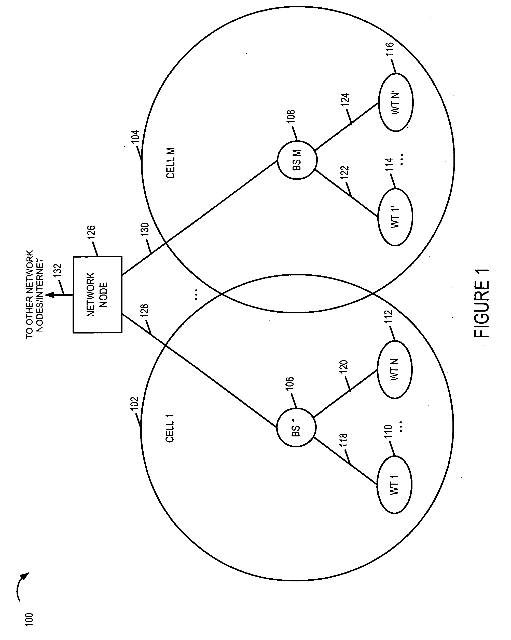
[0034]FIG. 1 is a drawing of an exemplary communications system 100, implemented in accordance with the present invention and using methods of the present invention. System 100 includes apparatus and methods directed to improving downlink communications by supporting a plurality of different downlink data rate option options and communicating a selected downlink data rate for a given downlink traffic channel segment in an efficient manner in accordance with the present invention. Exemplary system 100 may be, e.g., an orthogonal frequency division multiplexing (OFDM) multiple access wireless communication system. System 100 includes a plurality of cells (cell 1102, cell M 104). Each cell (cell 1102, cell M 104) represents a wireless coverage area for a corresponding base station (BS 1106, BS M 108), respectively. A plurality of wireless terminal (WTs) (WT 1110, WT N 112, WT 1′114, WT N′116) are included in system 100. At least some of the WTs are mobile nodes (MNs); the MNs may move ...


PUM


Abstract

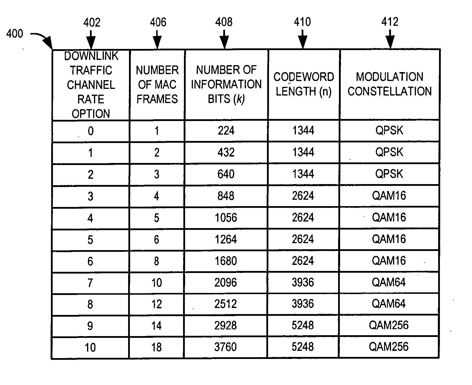
Downlink traffic channel data rate options and methods of indicating to a wireless terminal a utilized downlink data rate option are described. The downlink traffic channel rate option for a segment is conveyed using an assignment signal and / or a block in the downlink traffic channel segment which is not used for user data. Downlink segment assignment signals in some implementations allocate fewer bits for rate option indication than are required to uniquely identify each option. In some implementations low rate options, e.g., using QPSK, are uniquely identified via assignment signals. Higher rate options, e.g., using QAM16 modulation, are conveyed via the distinct information block in the downlink traffic segment using a first coding / modulation method. Still higher rate options, e.g., using QAM16, QAM64, or QAM256, are conveyed via the information block in the segment using a second coding / modulation method which is applied to the rate option information.

Description

RELATED APPLICATIONS [0001] The present application claims the benefit of U.S. Provisional Patent Application Ser. No. 60 / 701,313, filed on Jul. 20, 2005 which is hereby expressly incorporated by reference.FIELD OF THE INVENTION [0002] The present invention relates to methods and apparatus for indicating data rate option information while various exemplary embodiments are more particularly directed to indicating and using downlink data rate option information in a wireless communications system. BACKGROUND OF THE INVENTION [0003] In order to efficiently perform downlink traffic channel signaling in a wireless communications system, where a base station communicates with a plurality of wireless terminals, situated at different locations with different channel conditions and different levels of interference at any given time, it is beneficial to support a large number of data rate options for downlink traffic channel segments. Typically, in wireless communications systems supporting m...

Claims


Application Information

Patent Timeline
IPC IPC(8): H04Q7/00
CPCH04L1/0004H04L1/0005H04L1/0025H04L1/0029H04L1/0039H04L1/0046H04L2001/0098H04L1/0075H04L5/0053H04L27/0008H04L27/0012H04L27/2602H04L1/0057H04L1/0023H04L1/0003
Inventor LAROIA, RAJIVJIN, HUILI, JUNYILANE, FRANK A.RICHARDSON, TOM
Owner QUALCOMM INC
Learn More