Tamper resistant plug to prevent removal of wire from a conduit

a technology of tamper-resistant plugs and conduits, which is applied in the direction of connection contact materials, coupling device connections, instruments, etc., can solve the problems of increasing drag, and achieve the effect of preventing the removal of wires, increasing the drag on the wires, and easy and fast installation

Inactive Publication Date: 2007-01-25
CARLSON DONALD
View PDF13 Cites 19 Cited by
  • Summary
  • Abstract
  • Description
  • Claims
  • Application Information

AI Technical Summary

Benefits of technology

[0010] The tamper resistant plug of the present invention solves the problems and provides the benefits identified above. That is to say, the present invention discloses a tamper resistant plug for use in a section of conduit carrying one or more wires that is configured to allow the wire(s) to extend past the plug in a manner that prevents a person from removing the wire from the conduit. In a preferred embodiment of the present invention, the tamper resistant plug is easily and quickly installed at or near the end of a section of conduit in a manner that secures the wires against the inner surface of the conduit to increase the drag on the wires if they are pulled, thereby preventing removal of the wires from the conduit. The preferred embodiment of the tamper resistant plug of the present invention includes a mechanism to allow authorized persons to disengage the plug for removal from the conduit and / or pulling of the wires, while preventing unauthorized persons from doing the same. In the preferred embodiment, the present tamper resistant plug is adaptable to a wide range of conduit and wire sizes.
[0013] In the preferred embodiment, the biasing mechanism comprises an elongated connector having a proximal end disposed at the first rigid member and a distal end generally disposed at the second rigid member. The connector has a head member at its proximal end that engages the first rigid member to compress the engaging member. Preferably, the head member is of the type that is configured to be substantially tamper resistant or tamper proof, as utilized for tamper resistant screws or bolts that require a specially configured or proprietary bit to engage. In the preferred embodiment, the first rigid member has a recessed area on its proximal side that is shaped and configured to receive the head member therein. Preferably, the recessed area and the head member are cooperatively configured to further deter unauthorized removal of the connector from the engaging member. A threaded section at the distal end of the connector threadably attaches to the second rigid member aperture or to a nut or other connector element behind the second rigid member such that when the connector is operated / tightened it biases the first and second rigid connectors toward each other. This compresses the engaging member therebetween to radially extend its outer surface so as to engage the inner surface of the conduit and secure the wires generally between the engaging member and the inner surface of the conduit. This substantially increases the drag when someone attempts to pull on the wires, thereby preventing removal of the one or more wires from the conduit unless the person first disengages the tamper resistant plug from its engagement with the conduit. A retaining mechanism, such as a retainer ring, can engage the distal end of the connector to prevent any components, particularly the second rigid member, from falling off the tamper resistant plug when it is disengaged from the conduit.
[0014] Accordingly, the primary objective of the present invention is to provide a tamper resistant plug to prevent removal of wire from a conduit that provides the advantages discussed above and overcomes the disadvantages and limitations associated with presently available conduit plugs and conduit sealing mechanisms.
[0015] It is also an important object of the present invention to provide a tamper resistant plug that is configured to be received in and selectively engage a conduit carrying one or more wires in a manner that allows the wires to extend past the plug while preventing unauthorized removal or theft of the wires from the conduit.
[0016] It is also an important object of the present invention to provide a tamper resistant plug for use in conduit having one or more wires that prevents removal of the wires from the conduit unless a specially configured tool is utilized to first disengage the plug from the conduit.
[0018] It is also an important object of the present invention to provide a tamper resistant plug having a deformable engaging member disposed between a pair of rigid members that are biased toward each other so as to compress one or more wires between the engaging member and the inner surface of the conduit to prevent removal of the wires from the conduit.

Problems solved by technology

This substantially increases the drag when someone attempts to pull on the wires, thereby preventing removal of the one or more wires from the conduit unless the person first disengages the tamper resistant plug from its engagement with the conduit.

Method used


Image

  • Tamper resistant plug to prevent removal of wire from a conduit
  • Tamper resistant plug to prevent removal of wire from a conduit
  • Tamper resistant plug to prevent removal of wire from a conduit

Examples


Embodiment Construction

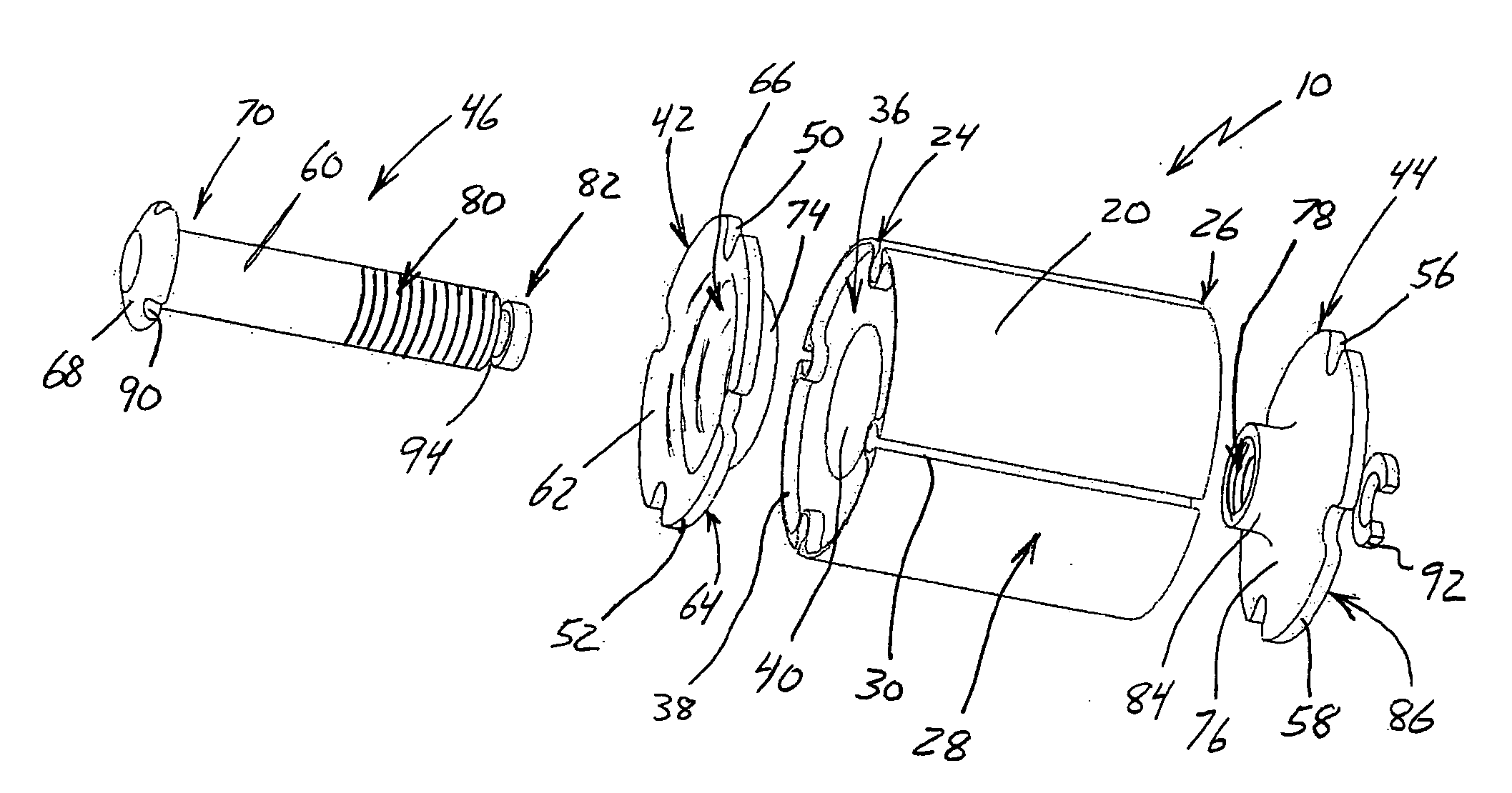
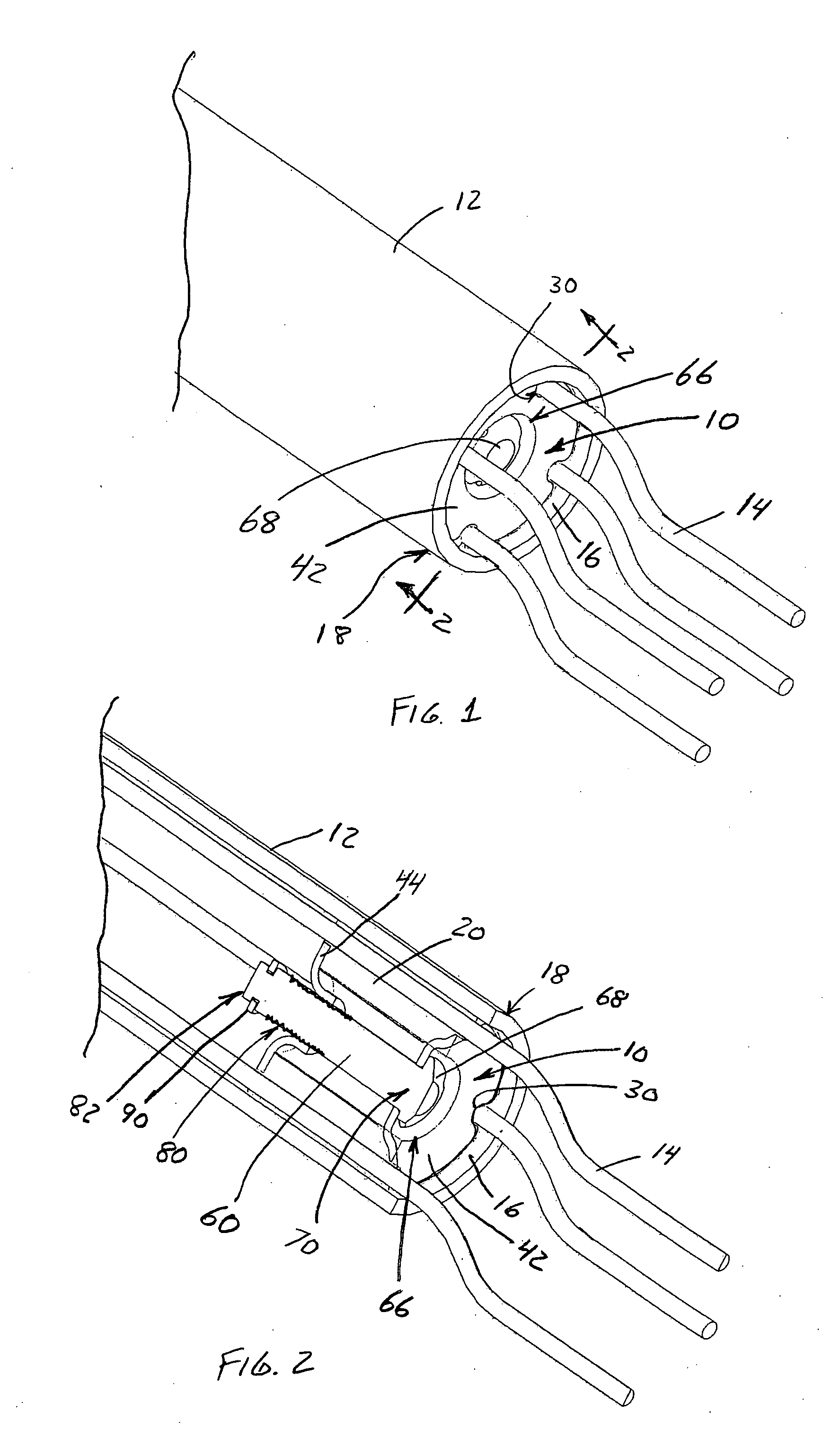
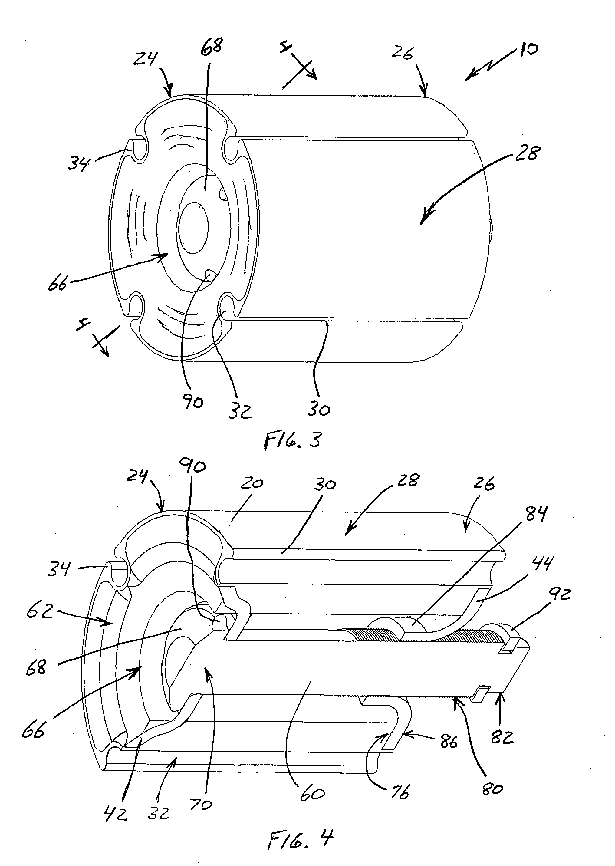
[0031] With reference to the figures where like elements have been given like numerical designations to facilitate the reader's understanding of the present invention, the preferred embodiments of the present invention are set forth below. The enclosed figures and drawings are merely illustrative of a preferred embodiment and represents one of several different ways of configuring the present invention. Although specific components, materials, configurations and uses are illustrated, it should be understood that a number of variations to the components and to the configuration of those components described herein and in the accompanying figures can be made without changing the scope and function of the invention set forth herein. For instance, although the figures and description provided herein are primarily described as being utilized to prevent the theft of electrical wires from a conduit, those skilled in the art will readily understand that this is merely for purposes of simpli...


PUM


Abstract

A tamper resistant plug configured to prevent unauthorized persons from pulling wires out of a conduit. The tamper resistant plug comprises a deformable, resilient engaging member that is operatively compressed by a compressing mechanism to radially extend its outer surface toward the conduit's inner surface. Each wire is received in a wire receiving groove on the outer surface of the engaging member such that compression of the engaging member tightly compresses the wires against the conduit to increase drag and prevent pulling the wires out of the conduit. The compression mechanism includes rigid members at each end of the engaging member and a biasing mechanism, preferably a bolt-like member that threadably connects to the distal rigid member or to a nut-like element, to bias the rigid members together. The head of the connector is configured to be tamper resistant and cooperatively engage the proximal rigid member to further prevent theft.

Description

CROSS-REFERENCE TO RELATED APPLICATIONS [0001] None. BACKGROUND OF THE INVENTION [0002] A. Field of the Invention [0003] The field of the present invention relates generally to devices for preventing removal of cable or wire from a conduit. More particularly, the present invention relates to such devices that are configured as a removable plug which is received in a conduit so as to prevent theft or other unauthorized removal of wire from the conduit. Even more particularly the present invention relates to such plug devices that are configured to effectively engage one or more wires in a conduit to prevent unauthorized removal of the wire behind the plug while allowing the wires to pass through the plug. [0004] B. Background [0005] Various electrically conductive metals are utilized for wires in wiring systems to transmit electricity or electrical signals from one location to another. The most common and popular of the electrically conductive metals is copper. Unfortunately, as the ...

Claims


Application Information

Patent Timeline
Patent Type & Authority Applications(United States)
IPC IPC(8): H01R13/648H01R4/66G06Q30/00
CPCA63B24/0075G06Q30/00H02G2200/10G09B7/00G09B5/00H01R13/59
Inventor CARLSON, DONALD
Owner CARLSON DONALD
Why Eureka
Try Eureka