Surgical handpiece with compact clutch and anti-wobble coupling head

a technology of coupling head and handpiece, which is applied in the field of handpieces, can solve the problems of increasing the overall length of the handpiece, making it difficult for surgeons to hold and precisely position the handpiece, and achieves the effect of minimizing the wiggle of the sha

Active Publication Date: 2007-01-25
STRYKER CORP
View PDF10 Cites 107 Cited by
  • Summary
  • Abstract
  • Description
  • Claims
  • Application Information

AI Technical Summary

Benefits of technology

[0015] Extending forward, the coupling head is formed with a stabilizing body. This spindle bore is shaped so that the body is tightly fitted in the adjacent section of the bore. In some preferred versions of the invention, the stabilizing body and complementary bore-defining shaft inner wall have circular cross sectional profiles. Owing to the tight fit of the shaft in the bore, wobble of the shaft is minimized.

Problems solved by technology

A disadvantage of this type of structure is that it increases the overall length of the handpiece.
The positioning of any mass away from a surgical handpiece's center of gravity / hand hold makes it more difficult for the surgeon to hold and precisely position the handpiece.
Other disadvantages are associated with known coupling assemblies used to releasably hold cutting accessories and attachments to the handpiece spindles.

Method used


Image

  • Surgical handpiece with compact clutch and anti-wobble coupling head
  • Surgical handpiece with compact clutch and anti-wobble coupling head
  • Surgical handpiece with compact clutch and anti-wobble coupling head

Examples


Embodiment Construction

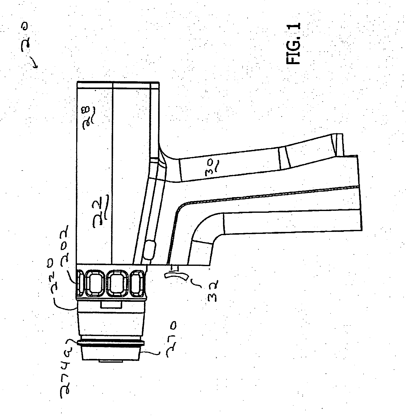
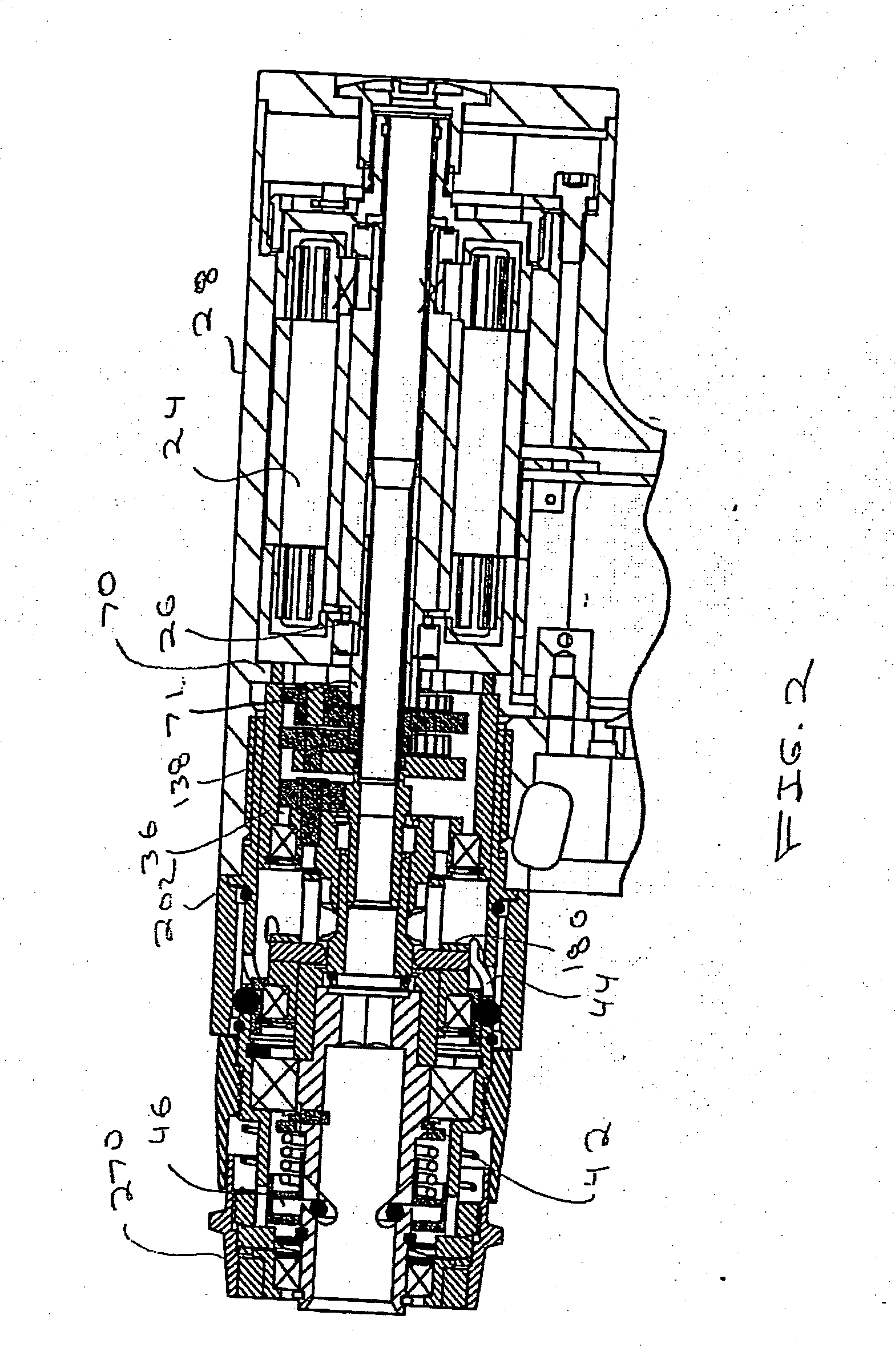
[0054]FIGS. 1 and 2 illustrate a rotary surgical handpiece 20 constructed in accordance with the invention. Handpiece 20 has a housing 22 in which in a motor 24 is seated. In one version of the handpiece 20, motor 24 is a DC motor. In other versions of the invention, motor 24 may be an AC motor, or a pneumatic or hydraulically driven motor. Integral with the motor 24 is rotating output shaft 26. Handpiece housing 22 is shaped to have a generally cylindrical head 28 in which motor 24 is fitted. Extending downwardly from head 28, handpiece housing 22 is shaped to have a handle 30 generally in the form of a pistol grip.

[0055] At least one trigger switch 32 extends distally forward from the front face of handle 30. (“Distal”, it shall be understood means toward the surgical site to which the handpiece 20 is directed. “Proximal”, means away from the surgical site.) A control circuit internal to the housing 22, (not illustrated and not part of this invention) monitors the actuation of th...


PUM


Abstract

A surgical handpiece with a rotating spindle for receiving the coupling head of a surgical attachment or a cutting accessory. A gear train has plural drive heads that simultaneously rotate at different speeds. A clutch assembly has pins that move along the length of the spindle. The clutch assembly sets the position of the pins so they will engage one of the drive heads. The spindle rotates with the drive head with which the clutch pins are engaged.

Description

RELATIONSHIP TO EARLIER FILED APPLICATION [0001] This application claims priority under 35 U.S.C. Sec. 119 from U.S. Provisional Pat. App. No. 60 / 693,638 filed 25 Jun. 2005.FIELD OF THE INVENTION [0002] This invention relates to a surgical handpiece able to accept different rotating attachments and cutting accessories. More particularly, this invention is related to a surgical handpiece with a clutch for transferring rotational moment from a drive assembly that is compact in size. This invention is further related to a surgical handpiece with a coupling head for receiving different attachments or accessories that minimizes attachment / accessory rotational wobble. BACKGROUND OF THE INVENTION [0003] In modern surgery, an important instrument available to medical personnel is the powered surgical tool. Often, this tool is a handpiece in which a motor is housed. Secured to the handpiece is a cutting accessory designed for application to a surgical site on a patient in order to accomplish...

Claims


Application Information

Patent Timeline
Patent Type & Authority Applications(United States)
IPC IPC(8): A61B17/32
CPCA61B17/32002A61B2017/00464A61B2017/00477A61B2017/00734A61B2017/320032B23B31/1074Y10T279/3418B25F5/001A61B17/162A61B17/1624A61B17/1631A61B17/1622B23B45/008B23B31/10741A61B17/1615A61B17/1628
Inventor BELAGALI, KRISHNAMURTHYWIEBE, JAMES B. III
Owner STRYKER CORP
Why Eureka
Try Eureka