Composite mattress assembly and method for adjusting the same

a mattress and mattress technology, applied in the field of composite mattress assembly and method, can solve the problems of high level of return, inability to replace components, and difficulty in improving the properties of zone and surface area,

Inactive Publication Date: 2007-02-01
AMERICAN PACIFIC PLASTIC FABTORS
View PDF7 Cites 104 Cited by
  • Summary
  • Abstract
  • Description
  • Claims
  • Application Information

AI Technical Summary

Benefits of technology

[0008] Accordingly, the present invention provides an improvement over the standard foam mattress, providing an alterable and reconfigurable composite mattress as described herein having a plurality of vertical zones, each formed beneath a respective horizontal sector, there being a plurality of horizont

Problems solved by technology

Thus, once the mattress is fabricated, the components are not replaceable.
For example, spring-based mattresses inherently have varying properties over their surface, and the variations of properties relating to zone and surface ar

Method used


Image

  • Composite mattress assembly and method for adjusting the same
  • Composite mattress assembly and method for adjusting the same
  • Composite mattress assembly and method for adjusting the same

Examples


Embodiment Construction

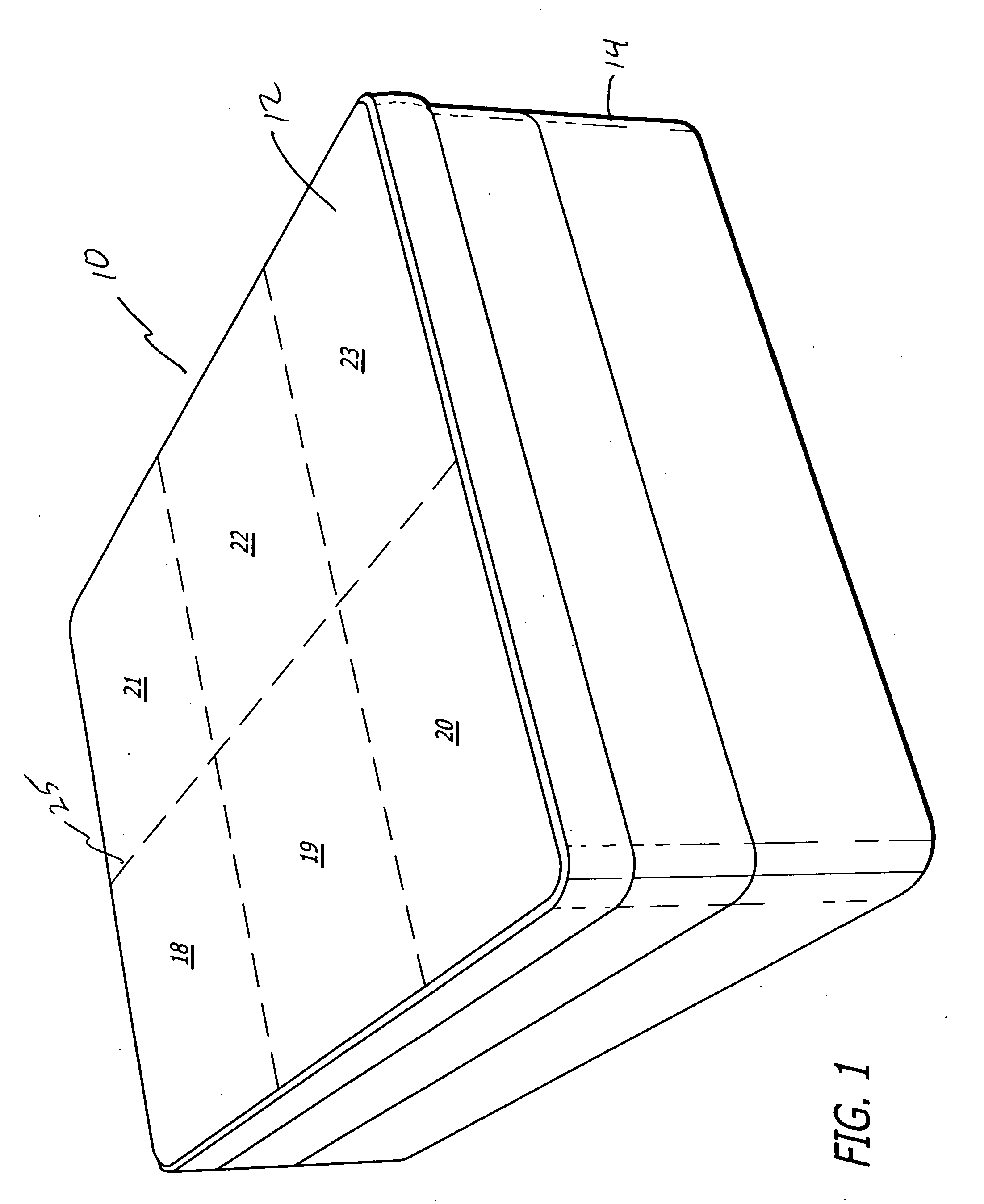
[0014] Mattress assemblies 10 according to aspects of the present design are shown in FIGS. 1-3. FIG. 1 shows a perspective looking down toward the upper surface 12 of a mattress assembly 10. It is shown as a mattress assembly 10 suitable for use by two persons. The mattress assembly 10 is shown on top of a box foundation 14.

[0015] For reference herein, the mattress assembly 10 has a first longitudinal phantom line 25 dividing the mattress into a left sector and a right sector. Further, horizontal phantom lines show the division of the mattress sectors into zones 18, 19, 20 and 21, 22, 23. Zones 18 and 21 will be located beneath the head and shoulders of a user; zones 19 and 22 beneath the torso; and zones 20 and 23 beneath the legs and feet. These regions of the mattress assembly 10 are intended to be configurable and thereby responsive to each of those respective parts of the body of the user(s).

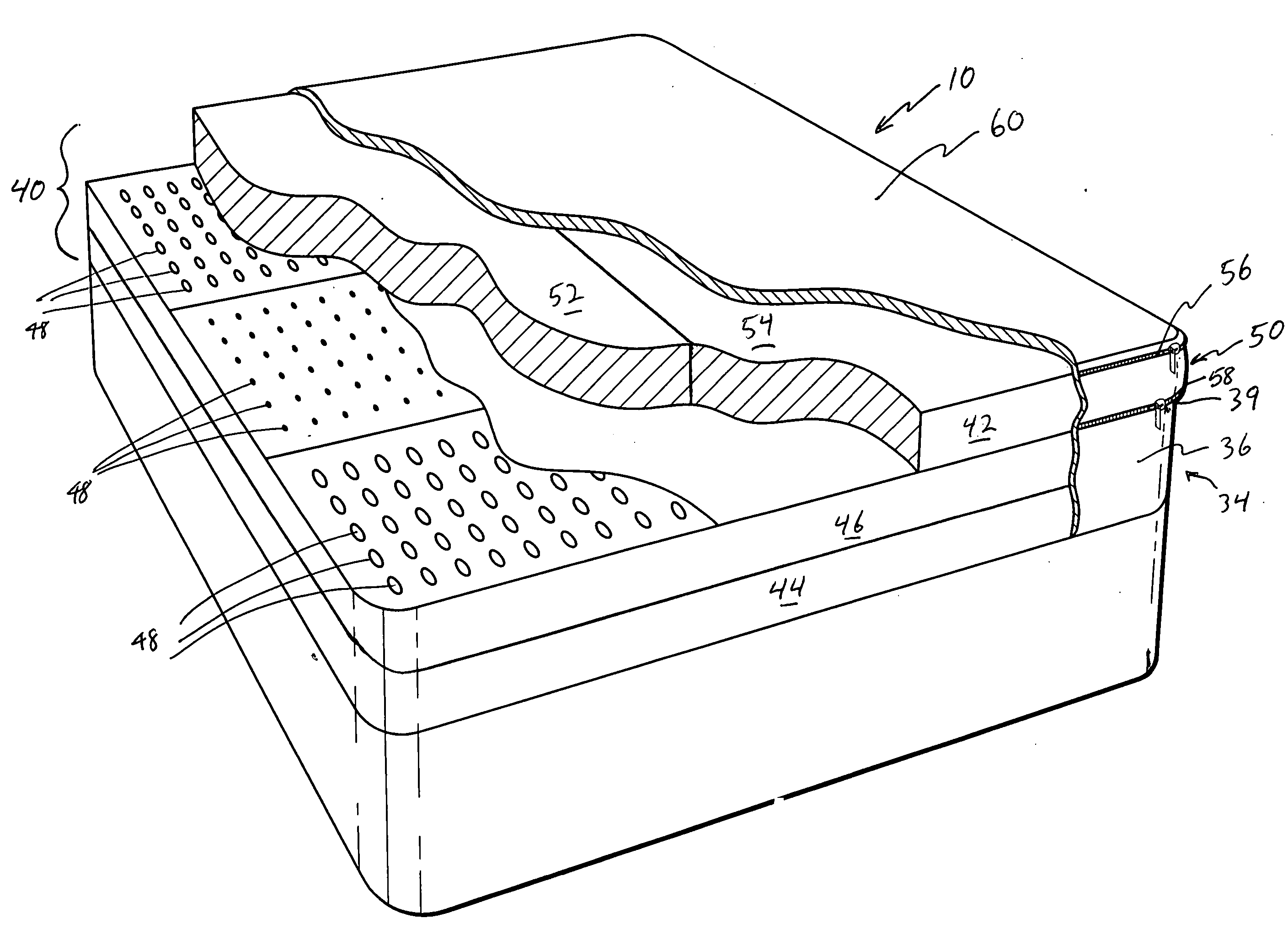
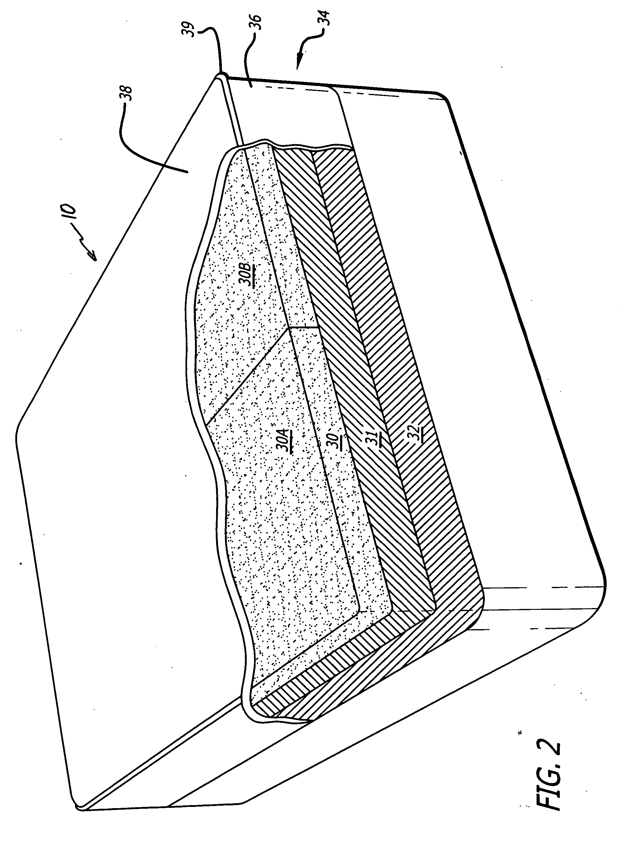
[0016]FIG. 2 shows a perspective, partially cut-away view of the mattress assembly 1...


PUM


Abstract

A composite mattress assembly has multiple layers, where one or more of the layers are foam layers and the rest are spring coil mattress layer(s). The composite mattress assembly may be made exclusively of foam layers as well. Any of the layers can be divided into two halves, which is divided longitudinally to support two people. Each half may independently have a layer which is made from a different material or different density or thickness in the case of a foam layer from that of the other half, according to two differing user preferences. A top casing is provided to encase the top layer, and a core casing is provided to enclose the bottom layers, where the two casings are zipped together along mating peripheral circumferential edge. Additionally, methods to adjust the firmness, temperature and the like of all of the foregoing composite mattress assembly are provided.

Description

RELATED APPLICATION [0001] This application is a CIP application of, and claims priority from, an earlier application, application Ser. No. 11 / 145,374 filed Jun. 3, 2005, entitled Composite Foam Mattress Assembly of the same sole inventor, Arthur A. Hochschild. The entire content of the earlier parent application is hereby incorporated by reference.BACKGROUND OF THE INVENTION [0002] Standard mattress designs have evolved very little in the past fifty years. A standard mattress generally includes a set of metal springs or coils mounted either on a base under a pad, or sandwiched in the center of a pair of pads. The metal springs and pad or pads are then covered with a strapping material. The entire structure is then sewn into a cloth cover and the edges are wrapped and sewn. Thus, once the mattress is fabricated, the components are not replaceable. The limitations of metal spring mattresses combined with improved quality and durability of foam products has lead to the relatively rece...

Claims


Application Information

Patent Timeline
IPC IPC(8): A47C27/15
CPCA47C27/001A47C27/144A47C31/105A47C27/15A47C27/148
Inventor HOCHSCHILD, ARTHUR A.
Owner AMERICAN PACIFIC PLASTIC FABTORS
Why Eureka
Try Eureka