

Crank handle for spinning reel
a spinning reel and crank handle technology, applied in the field of fishing tackles, can solve problems such as the unstable crank handle b>3/b>, and achieve the effect of high stability and durabl
- Summary
- Abstract
- Description
- Claims
- Application Information
AI Technical Summary
Benefits of technology
Problems solved by technology
Method used
Image

Examples
Embodiment Construction
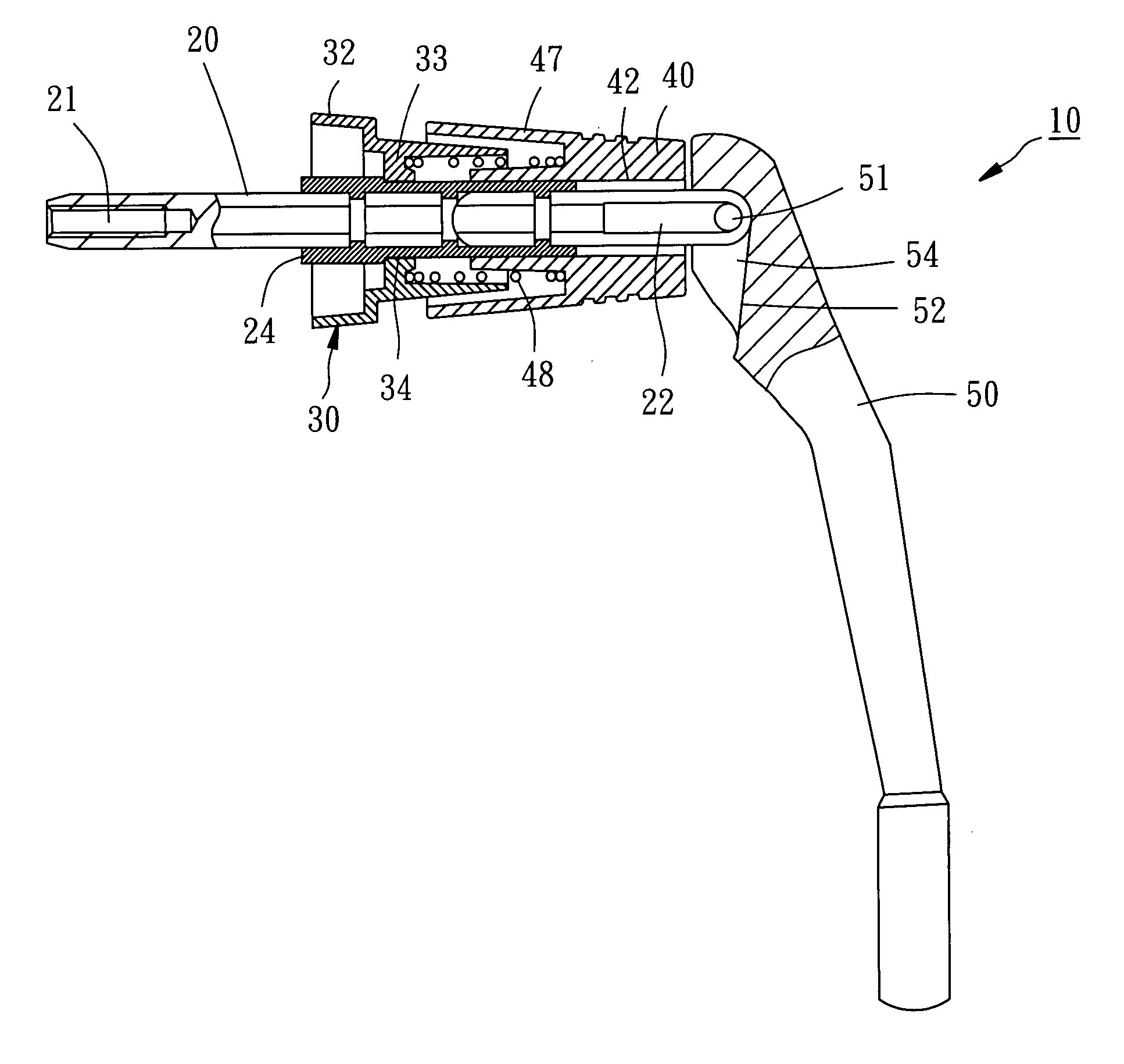
[0019] Referring to FIGS. 4-7, a crank handle 10 for a spinning reel in accordance with the first embodiment of the present invention is shown comprised of an axle 20, a base 30, a bush 24, a retaining member 40, a spring 48, and a handle 50.
[0020] The axle 20 has a screw hole 21 axially provided at one end thereof for fastening to the spinning reel with a screw (not shown), and two cut faces 22 longitudinally disposed at the other end thereof at two opposite sides. The axle 20 is a hexagonal rod member for engagement with other gear (not shown) in the spinning reel.
[0021] The base 30 comprises a tubular shell 32, a partition wall 33 transversely provided inside the tubular shell 32, and a through hole 34 provided at the partition wall 33 through which the axle 20 is inserted.
[0022] The bush 24 is sleeved onto the axle 20 and inserted into the through hole 34 of the base 30. The bush 24 is fixedly fastened to the axle 20 so that the bush 24 and the axle 20 can be rotated relative...
PUM
 Abstract
Description
Claims
Application Information