
Ion mobility spectrometer with parallel drift gas and ion carrier gas flows

a technology of ion carrier gas and mobility spectrometer, which is applied in mass spectrometers, isotope separation, particle separator tubes, etc., can solve the problems of difficult separation of ion species, high manufacturing cost, and inability to distinguish different ion species, so as to reduce the effort needed to set up a pattern data bank , the effect of low deflecting voltage and good separation efficiency of the ims

Active Publication Date: 2007-02-01
DRAGER SAFETY
View PDF5 Cites 12 Cited by
  • Summary
  • Abstract
  • Description
  • Claims
  • Application Information

AI Technical Summary

Benefits of technology

The present invention provides improvements over conventional techniques for analyzing chemical compositions using mass spectrometry (IMS). One improvement involves measuring changes in electrical current caused by variations in molecular structure during vaporization and detection processes. By adjusting the distance between different electrodes, researchers have been able to achieve better accuracy and precision in identifying specific compounds. Additionally, the use of multiple detectors has allowed for more accurate measurements without interference from nearby components. Other technical features include the ability to measure both positive and negative ions simultaneously, improved signal stability, reduced distortion of the measured spectrum, and increased flexibility in design options. These innovations make this method faster, easier, and more reliable for analyzing complex samples.

Problems solved by technology

The technical problem addressed in this patent text is the need for an improved ion mobility spectrometer that can detect and separate trace substances in the air, including explosives, illegal drugs, chemical warfare agents, and toxic industrial gases, with a high degree of accuracy and at a low cost. The current systems are expensive, complicated to manufacture, and can only be miniaturized with difficulty. Additionally, the patent text describes various methods for guiding and detecting ions, including unidirectional flow guiding, ionization in the drift chamber, and the use of high-frequency alternating fields. However, these methods have limitations, such as the need for high voltage, complicated signal evaluation, and susceptibility to ambient effects.

Method used


Image

  • Ion mobility spectrometer with parallel drift gas and ion carrier gas flows
  • Ion mobility spectrometer with parallel drift gas and ion carrier gas flows
  • Ion mobility spectrometer with parallel drift gas and ion carrier gas flows

Examples


Embodiment Construction

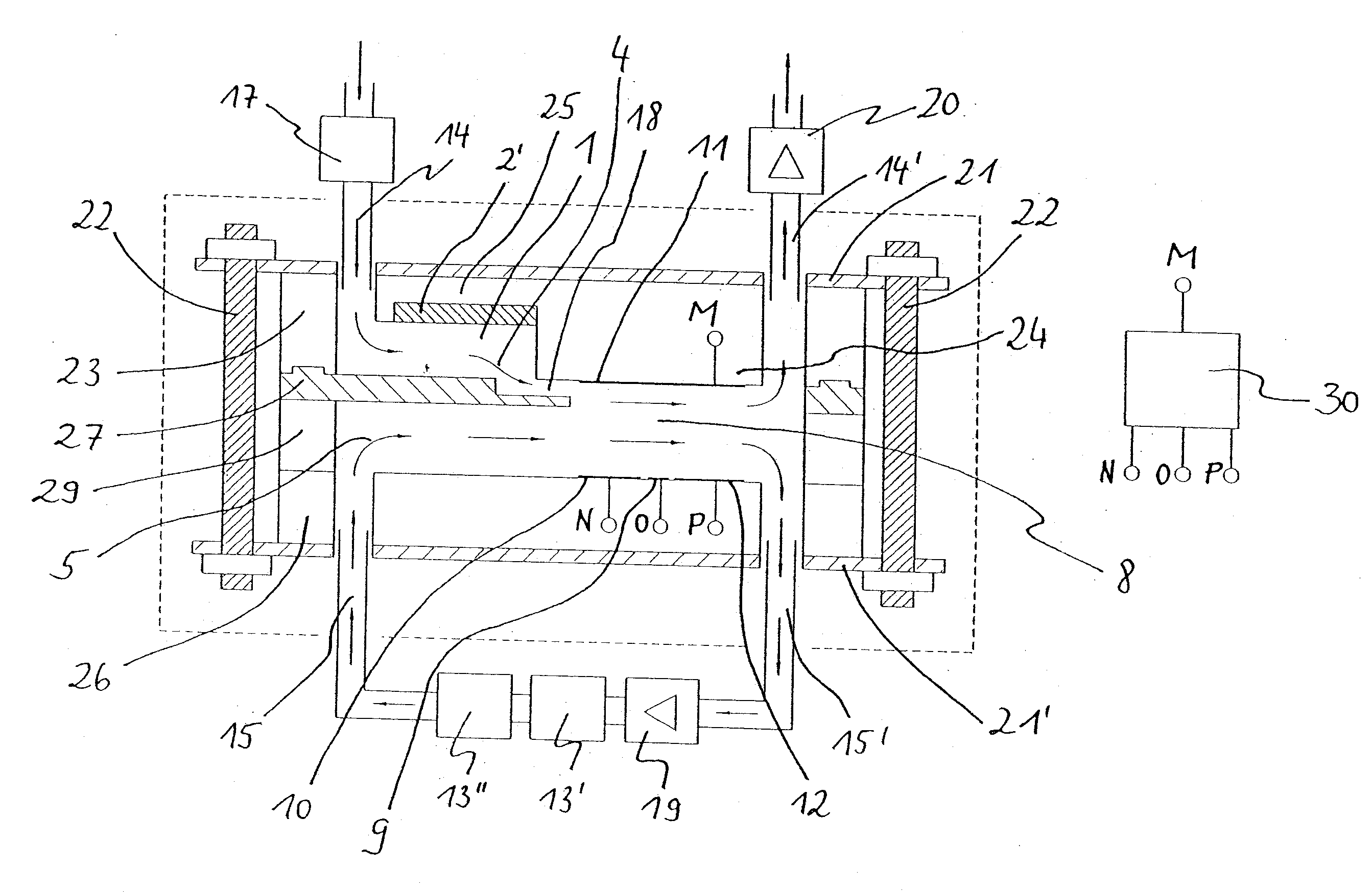
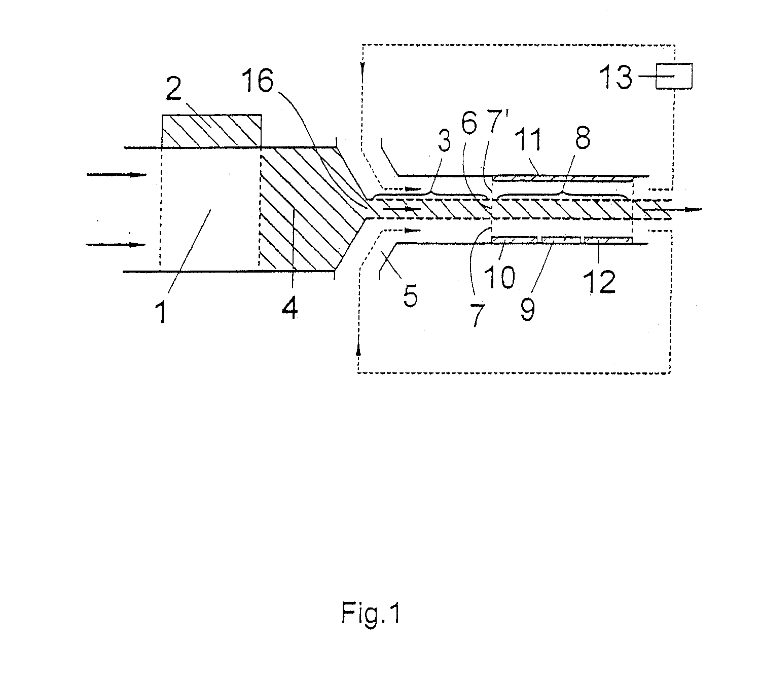
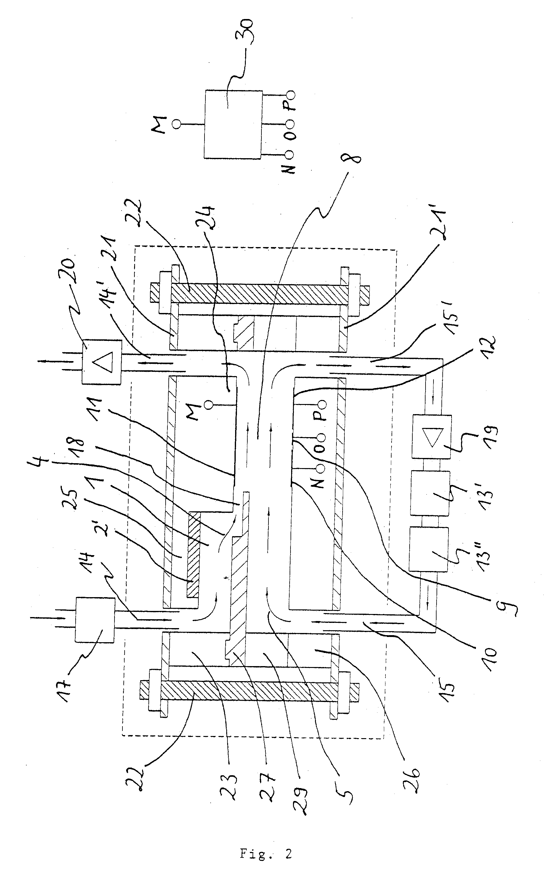
[0057] Referring to the drawings in particular, FIG. 1 shows in a schematic view, an ion mobility spectrometer according to the present invention. This ion mobility spectrometer requires only a relatively low voltage, which is on the order of magnitude of below 50 V, for separating the ions and can therefore be manufactured at low cost. The gas flows that occur are indicated by arrows.

[0058] The IMS comprises an ionization space 1, a radiation source 2, which emits beta radiation, and a transition area 3. Analyte-containing gas flowing through the ionization space is partially ionized under the effect of the beta radiation. As a result, ion carrier gas is formed in the sense of the present invention, which flows into the transition area 3. Furthermore, a nearly ion-free drift gas 5 is introduced into the transition area 3. Ion carrier gas 4 and drift gas 5 are introduced into the transition area 3 in such a manner that a flow becomes established at least at the end of the transitio...


PUM


Abstract

An ion mobility spectrometer is provided with at least one ionization chamber (1) through which analyte-containing gas can flow. A radiation source (2) is provided from which ionizing radiation is suitable for ionizing the analyte-containing gas at least partially, enters the ionization space (1). A separation area is located behind the ionization space (1) in the direction of flow, into which the partially ionized gas is admitted as an ion carrier gas (4) and a nearly ion-free gas is admitted as a drift gas (5) in such a way that a flow in which predominantly ion carrier gas (4) flows through cross-sectional areas (6) and predominantly drift gas (5) flows through other cross-sectional areas (7, 7′), becomes established at least in the inlet area of the separation area (8). The drift gas (5) and ion carrier gas (4) flow unidirectionally and the cross-sectional areas (6), through which predominantly ion carrier gas (4) flows, are smaller in at least one dimension than the cross-sectional areas (7, 7′), through which predominantly drift gas (5) flows.

Description


Claims


Application Information

Patent Timeline
Owner DRAGER SAFETY
Learn More