Eureka AIR delivers breakthrough ideas for toughest innovation challenges, trusted by R&D personnel around the world.

AC motor designed to ensure high efficiency in operation

Inactive Publication Date: 2007-02-01
DENSO CORP
View PDF8 Cites 7 Cited by
  • Summary
  • Abstract
  • Description
  • Claims
  • Application Information

AI Technical Summary

Benefits of technology

[0009] It is an object of the invention to provide an improved structure of ac motor which is designed to ensure high efficiency in operation and allowed to be reduced in size and manufactured at low costs.
[0010] According to one aspect of the invention, there is provided an ac motor which comprises: (a) a rotor having rotor magnetic poles which are N-poles and S-poles arranged alternately along a circumference thereof; (b) a stator having N stator pole groups made up of magnetic poles arranged along a circumference thereof, the N stator pole groups being shifted in a circumferential direction of the stator relatively from a preselected reference one of the rotor magnetic poles by different angles, respectively, on a pole basis; and (c) a plurality of looped windings each of which extends in a circumferential direction of the stator. The looped windings are disposed adjacent each other in an axial direction of the stator in relation to the N stator pole groups, respectively. The number P of the rotor magnetic poles and the number M of the magnetic poles of the stator are selected to meet a relation of M<(P / 2)×N. This structure permits the number of the magnetic poles of the stator to be decreased as compared with a prior art structure, which ensures desired air gaps between the magnetic poles of the stator, thus minimizing a leakage of magnetic flux between the magnetic poles of the stator to increase torque to be outputted by the motor.

Problems solved by technology

This structure encounters the drawback in that each of the windings needs to be placed deep in one of slots between the stator magnetic poles, thus resulting in limited numbers of turns of the windings, and has difficulties in permitting the motor to be reduced in size and produced at low costs and in improving torque-producing efficiency.

Method used


Image

  • AC motor designed to ensure high efficiency in operation
  • AC motor designed to ensure high efficiency in operation
  • AC motor designed to ensure high efficiency in operation

Examples


Embodiment Construction

[0048] Japanese Patent First Publication No. 2005-160285 that is an equivalent to US2005 / 0099082 A1 filed Nov. 8, 2004, assigned to the same assignee as that of this application, discloses an AC motor and its motor controller having structures similar to those described below, the disclosure of which is incorporated totally herein by reference.

[0049] Prior to describing the structure of a brushless motor of the invention, related technologies will be discussed below.

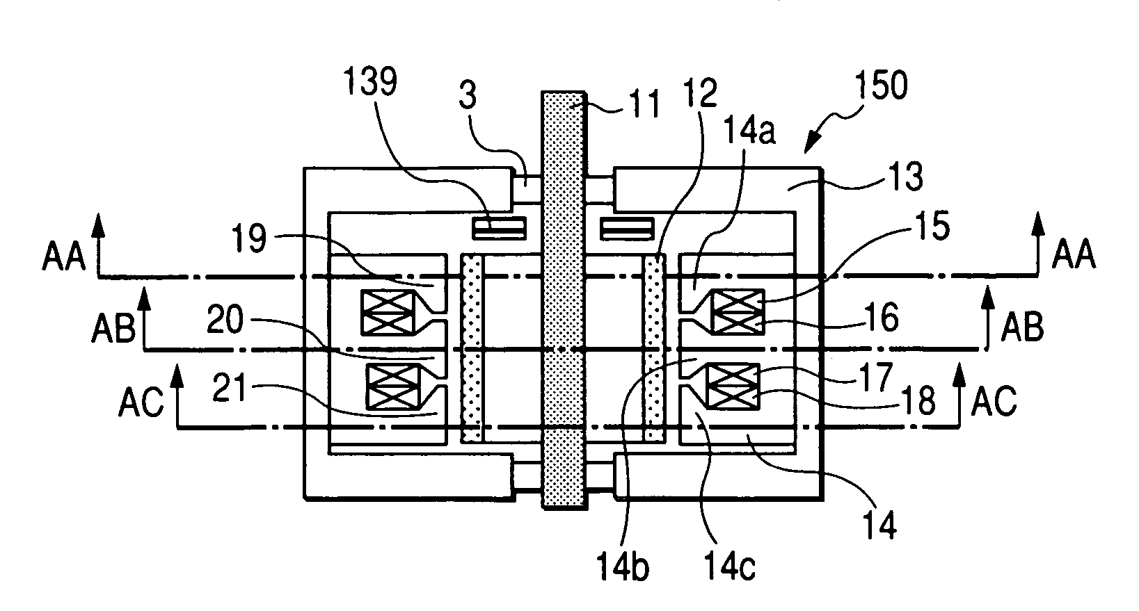
[0050]FIG. 1 shows a brushless motor 150 which may be employed in passenger automobiles or autotrucks.

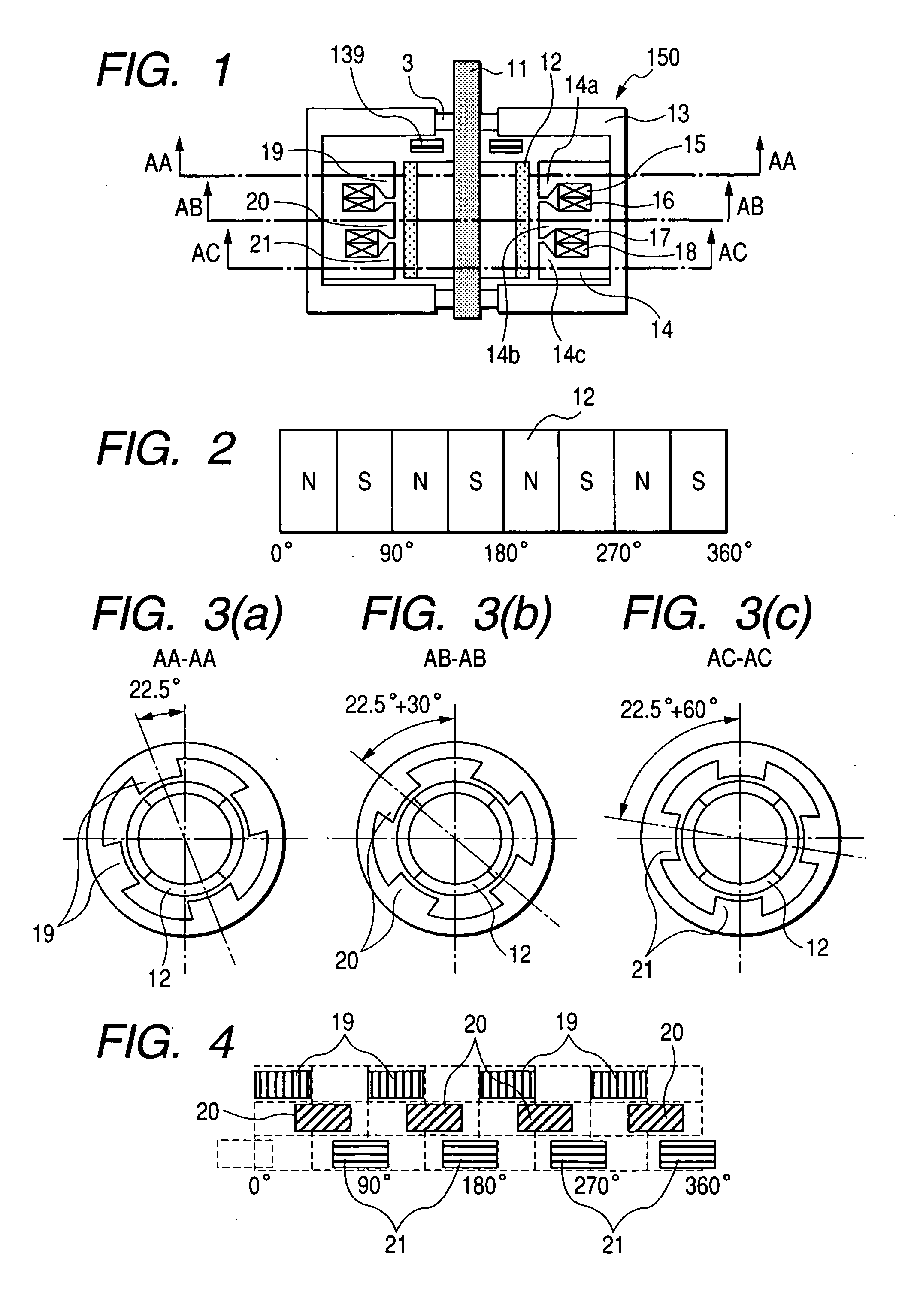
[0051] The brushless motor 150 is an 8-pole brushless motor operating on three-phase AC current and includes a rotor 11 and a stator 14.

[0052] The rotor 11 has a plurality of permanent magnets 12 disposed around the outer surface thereof. The permanent magnets 12 have north (N) and south (S) poles arrayed alternately along the circumference of the rotor 11. FIG. 2 is a development of the rotor 11 in the circumferenti...


PUM


Abstract

An ac motor is provided which includes a plurality of looped windings each of which extends in a circumferential direction of a stator. The stator is equipped with N stator pole groups made up of magnetic poles arranged along a circumference thereof. The looped windings are disposed adjacent each other in an axial direction of the stator. The number P of the rotor magnetic poles and the number M of the magnetic poles of the stator are selected to meet a relation of M<(P / 2)×N. This structure permits the number of the magnetic poles of the stator to be decreased, which ensures desired air gaps between the magnetic poles of the stator, thus minimizing a leakage of magnetic flux between the magnetic poles of the stator to increase torque to be outputted by the motor.

Description

CROSS REFERENCE TO RELATED DOCUMENT [0001] The present application claims the benefits of Japanese Patent Application No. 2005-222738 filed on Aug. 1, 2005, the disclosure of which is incorporated herein by reference. BACKGROUND OF THE INVENTION [0002] 1. Technical Field of the Invention [0003] The present invention relates generally to an ac electric motor for use in passenger automobiles or autotrucks, and more particularly to such a motor designed to ensure high efficiency in operation and to be allowed to be reduced in size and manufactured at low costs. [0004] 2. Background Art [0005] Japanese Patent First Publication No. 6-261513 discloses a brushless motor equipped with multiple phase windings each of which wound around a stator magnetic pole in the form of a concentrated winding. This structure encounters the drawback in that each of the windings needs to be placed deep in one of slots between the stator magnetic poles, thus resulting in limited numbers of turns of the windi...

Claims


Application Information

Patent Timeline
IPC IPC(8): H02K37/14H02K17/00
CPCH02K1/278H02K21/16H02K3/28H02K1/2781
Inventor MAKITA, SHINJINASHIKI, MASAYUKI
Owner DENSO CORP
Why Eureka
Eureka Blog
Learn More