
All-Optical CSMA/CD Apparatus In Base A Ethernet And The Method Therefor

Inactive Publication Date: 2009-05-14
GWANGJU INST OF SCI & TECH
View PDF6 Cites 2 Cited by
  • Summary
  • Abstract
  • Description
  • Claims
  • Application Information

AI Technical Summary

Benefits of technology

[0012]The invention has the following effects. It is possible to check, by using the mutual gain saturation of a semiconductor optical amplifier of a central office, whether distortion occurs in two or more optical signals due to mutual interference when the optical signals pass through the SOA at the same time, to amplify the optical signals that are transmitted in the upward direction when no distortion occurs in the optical signals, and to monitor the occupation of a plurality of subscribers with respect to the common network when the plurality of subscribers want to use an optical Ethernet network. In this way, in each ONU, it is possible to dynamically check whether a collision between the optical signals passing through the common network occurs and whether the optical signals are successfully transmitted and thus to determine whether to retransmit the optical signals or whether to transmit the next information in a standby state.
[0013]Further, since the Ethernet-based CSMA / CD apparatus according to the present invention is an all-optical type, the existing electric media access control (MAC) device is not needed, which results in a high-speed operation. In addition, the Ethernet-based CSMA / CD apparatus according to the present invention can be used for a plurality of subscribers using an inexpensive light source. Further, since an optical receiver of the central office and all ONUs can simultaneously check whether a collision between optical signals occurs in the common network, optical lines can be dynamically connected. Furthermore, the invention can be applied to an intelligent optical Ethernet network capable of dynamically monitoring the state of the common network.

Problems solved by technology

However, an additional circuit is needed to check whether the distortion occurs, and the check is performed in an electric area, resulting in a time delay.
Therefore, the method is not suitable for a high-speed optical Ethernet environment in which a large amount of data is transmitted at high speed.
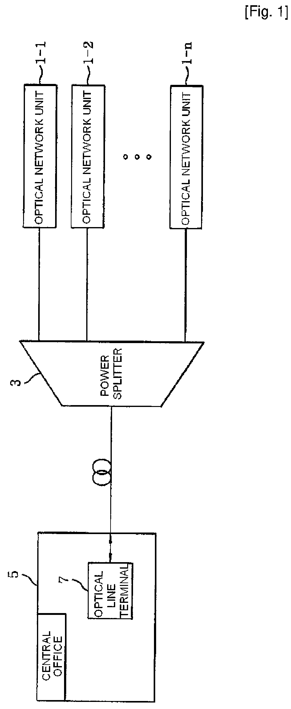
However, the technique is excellent in transmission efficiency, but cannot solve the above-mentioned problem when distances between the PS 3 and subscribers are different from each other or when optical outputs from the ONUs are different from each other.
However, when input optical power varies due to a change in an optical path, an error in detecting distortion occurs.
AWGR is suitable for a wavelength-division-type optical network, but is not suitable for a passive optical network (PON) using a single upstream wavelength.
The above-mentioned methods enable a plurality of optical network units to use a common network in realizing an optical network, but do not consider the monitoring of the common network and the monitoring of distortion by the central office.

Method used


Image

  • All-Optical CSMA/CD Apparatus In Base A Ethernet And The Method Therefor
  • All-Optical CSMA/CD Apparatus In Base A Ethernet And The Method Therefor
  • All-Optical CSMA/CD Apparatus In Base A Ethernet And The Method Therefor

Examples


Embodiment Construction

[0022]Hereinafter, preferred embodiments of the invention will be described in detail with reference to the accompanying drawings. Objects, a, may be understood more readily by those skilled in the art

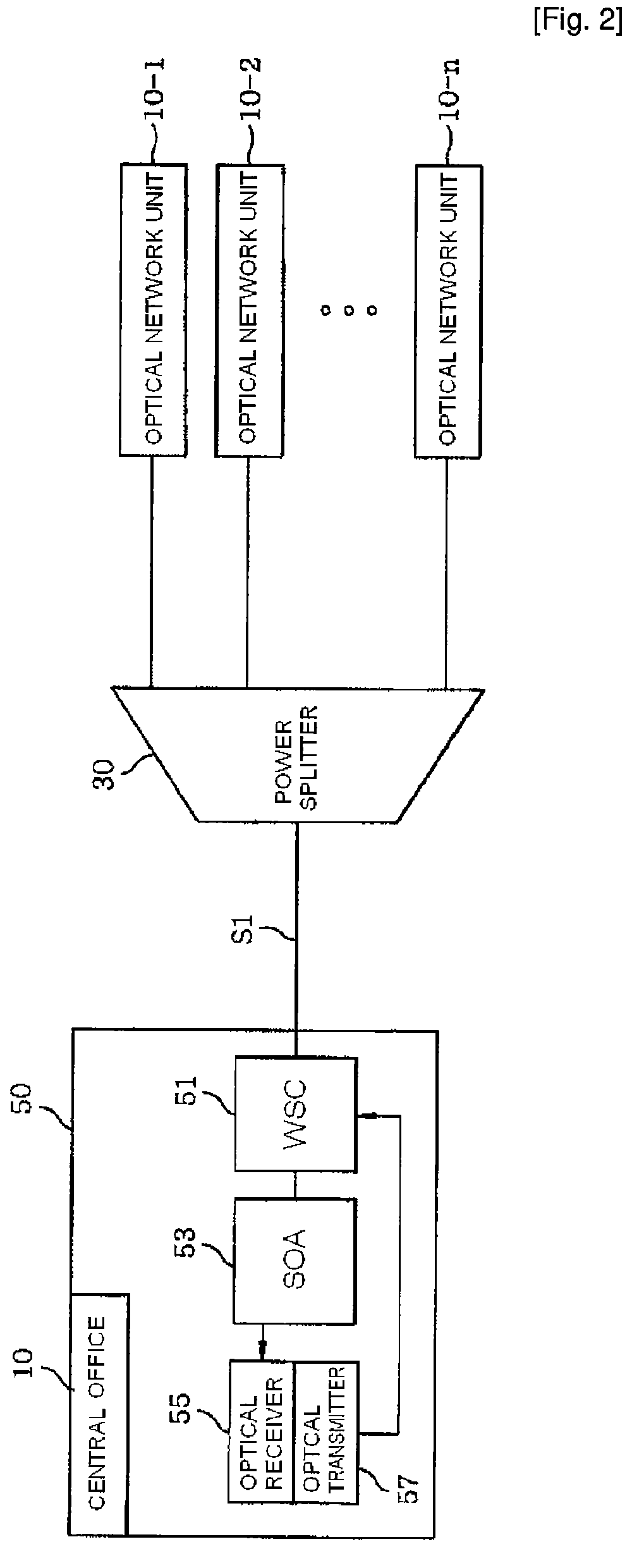
[0023]FIG. 2 is a block diagram illustrating an Ethernet-based all-optical CSMA / CD (carrier sense multiple access / collision detection) apparatus according to an embodiment of the invention. The Ethernet-based all-optical CSMA / CD apparatus according to the embodiment of the invention includes: a plurality of optical network units (ONUs) 10-1, 10-2, . . . , 10-n that transmit to a power splitter (PS) 30 upstream waves λU that are in a gain bandwidth of a semiconductor optical amplifier (SOA) 53 and are carried with different optical signals; the PS 30 that multiplexes different optical signals supplied from the plurality of ONUs 10-1, 10-2, . . . , 10-n, transmits the multiplexed optical signals to a central office (CO) 50, and transmits an optical signal supplied from a WSC (wavelength ...


PUM


Abstract

The invention relates to an Ethernet-based all-optical carrier sense multiple access / collision detection apparatus and method, and more particularly, to an apparatus and method capable of checking by using mutual gain saturation whether distortion occurs in two or more optical signals due to mutual interference when the optical signals pass through a semiconductor optical amplifier (SOA) at the same time, amplifying the optical signals transmitted in the upward direction when no distortion occurs in the optical signals, and monitoring the occupation of a plurality of subscribers with respect to a common network when the plurality of subscribers want to use an optical Ethernet network. The Ethernet-based all-optical carrier sense multiple access / collision detection apparatus according to the invention includes: a plurality of optical network units (ONUs) that carry different optical signals on upstream waves λ and transmit the upstream waves λ; a power splitter (PS) that multiplexes the optical signals and transmits the multiplexed optical signals; and a central office (CO) that checks whether the multiplexed optical signals are distorted, amplifies some of the checked optical signals, returns the other optical signals, and monitors the occupation of the plurality of optical network units with respect to a common network. According to the invention, it is possible to dynamically check whether a collision between the optical signals passing through the common network occurs and whether the optical signals are successfully transmitted. Further, since the invention uses an all-optical type, the existing electric media access control (MAC) device is not needed, which results in a high-speed operation. In addition, the invention can be used for a plurality of subscribers using an inexpensive light source. Thus, the invention can be effectively used for an optical communication industry.

Description

TECHNICAL FIELD[0001]The invention relates to an All-optical CSMA / CD apparatus in base a ethernet and the method therefore, and more particularly, to an apparatus and method capable of checking by using mutual gain saturation whether distortion occurs in two or more optical signals due to mutual interference when the optical signals pass through a semi-conductor optical amplifier (SOA) at the same time, amplifying the optical signals transmitted in the upward direction when no distortion occurs in the optical signals, and monitoring the occupation of a plurality of subscribers with respect to a common network when the plurality of subscribers want to use an optical Ethernet network.BACKGROUND ART[0002]As known in the related art, in an Ethernet-based network, a semiconductor optical amplifier (SOA) of a central office (CO) is an amplifier having a bidirectional amplifying characteristic, in which holes and electrons are rapidly recombined When different modulating signals are input ...

Claims


Application Information

Patent Timeline
IPC IPC(8): H04B17/00
CPCH04L12/2602H04L12/2856H04L12/40006H04Q2011/0079H04L43/00H04Q11/0067H04L12/413H04B10/07H04L12/28H04B10/25
Inventor PARK, CHANG SOOHAN, SOO WOOKKIM, TAE YOUNGYUN, HYUN HO
Owner GWANGJU INST OF SCI & TECH
Learn More