
Liquid-droplet jetting apparatus and liquid transporting apparatus

Active Publication Date: 2007-02-01
BROTHER KOGYO KK
View PDF6 Cites 3 Cited by
  • Summary
  • Abstract
  • Description
  • Claims
  • Application Information

AI Technical Summary

Benefits of technology

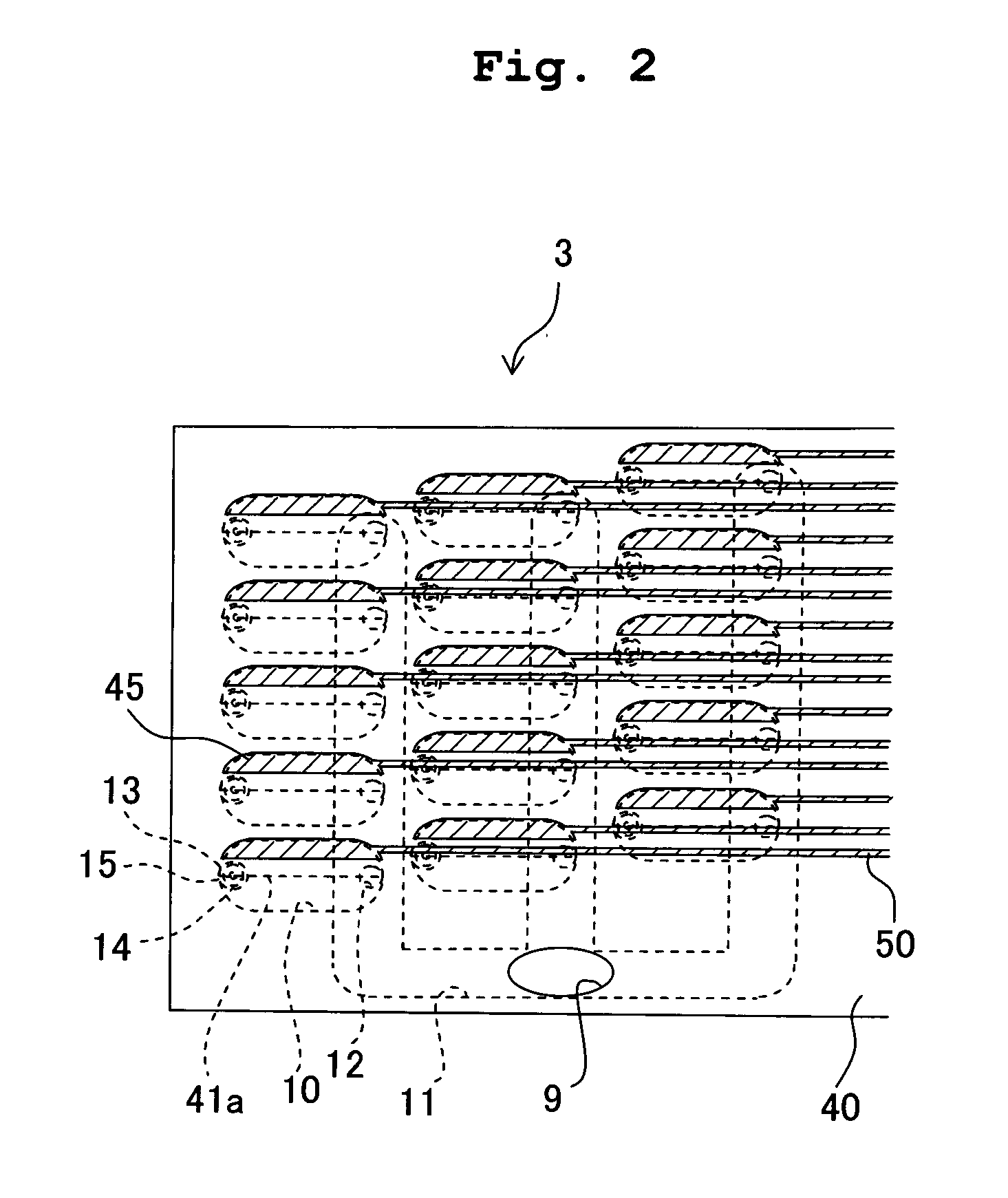
[0011] An object of the present invention is to provide a liquid-droplet jetting apparatus and a liquid transporting apparatus having a high durability and less power consumption, in which a wiring corresponding to the pressure chambers arranged highly densely can be realized.

Problems solved by technology

Therefore, there is a fear that the durability of a piezoelectric layer is declined.
Further, electric power consumption is also increased.
Therefore, when the pressure chambers are to be arranged highly densely, drawing of the wiring connecting each of the individual electrodes and the driver IC becomes very difficult.
Particularly, when the pressure chambers are to be arranged in a large number of rows, for example, in not less than three rows, the drawing of the wiring from an individual electrode corresponding to a pressure chamber arranged in an inner row among the rows becomes problematic.
However, this method lacks reliability of mechanical connection because the strength of connections is very weak.

Method used


Image

  • Liquid-droplet jetting apparatus and liquid transporting apparatus
  • Liquid-droplet jetting apparatus and liquid transporting apparatus
  • Liquid-droplet jetting apparatus and liquid transporting apparatus

Examples


first modified embodiment

[0088] As shown in FIG. 12, any recess may not be formed on a lower surface of an electroconductive substrate 62 of a vibration plate 60, and a thickness of the electroconductive substrate 62 may be uniform. In this case also, according to the result of stimulation shown in FIGS. 7 and 9, it is possible to generate the electric potential difference between the individual electrode 45 and the common electrode 44 to deform the vibration plate 60, thereby increasing the volume of the pressure chamber 10. Accordingly, it is possible to perform the pulling ejection without previously deforming the vibration plate 60 by generating the electric potential difference between the individual electrode 45 and the common electrode 44.

second modified embodiment

[0089] A vibration plate 65 may be formed of an insulating material as shown in FIG. 13. In this case also, it is possible to form the wiring 50 in a portion not overlapping with the piezoelectric layer 41, the portion included in an area overlapping with the pressure chamber 10 and on a surface of the vibration plate 65. Accordingly, the wirings 50 can be arranged highly densely. Further, in this case, a recess 65a is formed in the area, on the lower surface of the vibration plate 65, which overlaps with each of the pressure chambers 10. The recess 65a extends, from an edge of each of the pressure chambers 10 in the width direction thereof, toward the center of the pressure chamber 10 in the width direction thereof, the edge being on the side opposite to the other edge, of the pressure chamber, which overlaps with the piezoelectric layer 41. Thus, a portion of the vibration plate 65, in which the recess 65a is formed, is easily deformed. Furthermore, a through hole 65b is formed in...


PUM


Abstract

An ink-jet head includes a channel unit having pressure chambers; and a piezoelectric actuator which includes a vibration plate having an electroconductive substrate and an insulating layer, a piezoelectric layer arranged in an area overlapping with the pressure chamber, and a common electrode and an individual electrode formed on the piezoelectric layer. A recess is formed in an area overlapping with the pressure chamber. A wiring connected to the individual electrode is formed on the upper surface of the vibration plate in an area in which the piezoelectric layer is not formed. Accordingly, there is provided a liquid-droplet jetting apparatus and a liquid transporting apparatus having an improved durability, requiring a less electric power consumption, capable of performing a pulling ejection, and in which a wiring can be performed highly densely.

Description

CROSS REFERENCE TO RELATED APPLICATION [0001] The present application claims priority from Japanese Patent Application No. 2005-216707, filed on Jul. 27, 2005, the disclosure of which is incorporated herein by reference in its entirety. BACKGROUND OF THE INVENTION [0002] 1. Field of the Invention [0003] The present invention relates to a liquid-droplet jetting apparatus which jets liquid droplets, and a liquid transporting apparatus which transports a liquid. [0004] 2. Description of the Related Art [0005] Among ink-jet heads (liquid-droplet jetting apparatuses) which perform recording on a recording medium by applying pressure to an ink in a pressure chamber communicating with a nozzle to discharge the ink from the nozzle, there is an ink-jet head in which a vibration plate arranged to cover a pressure chamber is deformed by a piezoelectric actuator so as to apply pressure to an ink in the pressure chamber. For example, in an ink-jet head described in FIG. 3 of U.S. Patent Applicat...

Claims


Application Information

Patent Timeline
IPC IPC(8): B41J2/045
CPCB41J2/14233B41J2202/11B41J2002/14491
Inventor TAKAHASHI, YOSHIKAZU
Owner BROTHER KOGYO KK
Learn More