Computer readable medium recording a calibration program, calibration method, and calibration system

a computer readable medium and calibration method technology, applied in the field of computer readable medium recording a calibration program, calibration method and calibration system, can solve the problems of inaccurate changes in the state of the engine and other portions which actually perform image formation on printing media, and changes in the environment and aging of various portions, etc., to achieve accurate detection of the position of the above-described patch pattern, the effect of higher precision

Inactive Publication Date: 2007-02-01
SEIKO EPSON CORP
View PDF5 Cites 21 Cited by
  • Summary
  • Abstract
  • Description
  • Claims
  • Application Information

AI Technical Summary

Benefits of technology

[0012] Hence an object of this invention is to provide a computer readable medium recording a calibration program to adjust the output density of an image formation device, which can accurately detect each patch position during acquisition of calorimetric values from a patch sheet during this calibration, and can execute calibration with higher precision than in methods of the prior art.
[0013] In order to attain the above object, according to an aspect of the invention, a computer readable medium recording a calibration program, which causes a control device to perform calibration processing of reading as image data a patch sheet, output from an image formation device, having a plurality of patch patterns formed as images based on different density-gradation value data for each color, acquiring colorimetric values for each of the patch patterns from the read-out image data, and adjusting the density of the image formation device based on the density-gradation values and the acquired calorimetric values for each of the patch patterns, causes the control device to execute displaying the read-out image data of the patch sheet; detecting and displaying the position of each patch pattern in the image data of the patch sheet; and, acquiring the calorimetric value for each patch pattern based on the displayed patch pattern positions, in response to confirmation input by a user of the displayed positions of patch patterns. Hence by means of the invention, the positions of patch patterns detected by the control device can be confirmed by the user on a display screen, and after confirming that patch pattern positions have been accurately detected, the user can issue an instruction to acquire the calorimetric values. Hence reduction of calibration precision due to failures in patch pattern position detection can be avoided.

Problems solved by technology

However, when used in such an image formation device, changes with the environment and aging of various portions occur, and changes in the state of the engine and other portions which actually perform image formation on printing media occur.
In this case, when the output from the image formation device is quite thin (light), even when using the above-described marker patch method of the prior art, the marker patch itself, or the position of the marker patch cannot be accurately detected, and detection of the positions of the above-described patch patterns becomes inaccurate.

Method used


Image

  • Computer readable medium recording a calibration program, calibration method, and calibration system
  • Computer readable medium recording a calibration program, calibration method, and calibration system
  • Computer readable medium recording a calibration program, calibration method, and calibration system

Examples


Embodiment Construction

[0033] Below, embodiments of the invention are explained, referring to the drawings. However, the technical scope of the invention is not limited to these aspects, but extends to the inventions described in the scope of claims, and to inventions equivalent thereto.

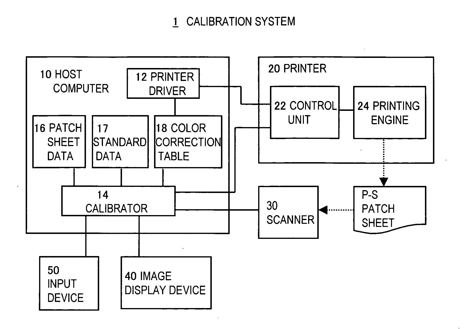
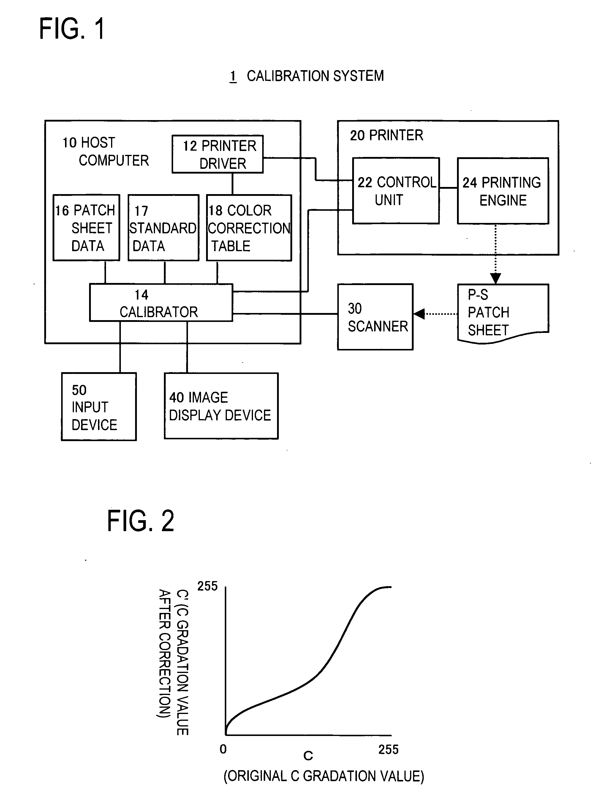
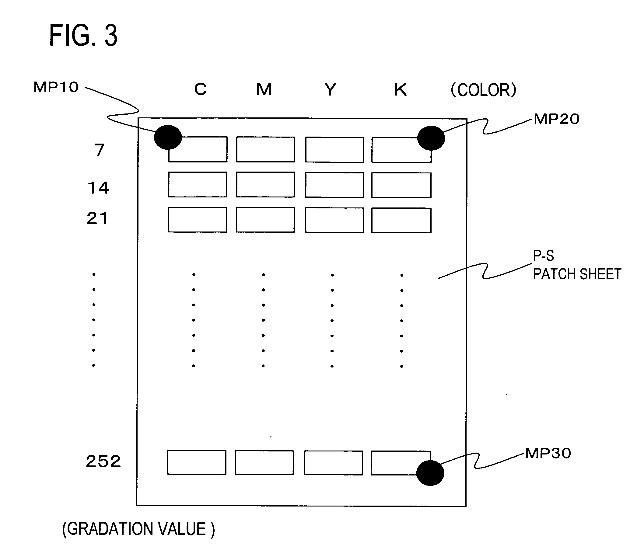
[0034]FIG. 1 shows in summary the configuration of an embodiment of a calibration system to which the invention is applied. The calibration system 1 shown in FIG. 1 is the system of this embodiment, and comprises a calibrator 14, which handles the main processing for calibration; a printer 20, which is the object for calibration; and a scanner 30, for color measurements. In this calibration system 1, the scanner 30 reads an output patch sheet P-S, and thereafter a color correction table 18 is updated based on the calorimetric values read out for each patch pattern PP; an interface is provided for modification and confirmation by the user of detected positions of the read-out patch patterns PP; and through error-free posit...


PUM


Abstract

A computer readable medium records a calibration program, which causes a control device to execute calibration processing of reading as image data a patch sheet output from an image formation device, having a plurality of patch patterns formed as images based on different density-gradation value data for each color, acquiring calorimetric values for each of the patch patterns from the read-out image data, and adjusting the density of the image formation device based on the density-gradation values and the acquired calorimetric values for each of the patch patterns. The program causes the control device to execute displaying the read-out image data of the patch sheet, detecting and displaying the position of each of the patch patterns in the image data of the patch sheet, and acquiring the calorimetric values for each the patch pattern based on the displayed patch pattern positions, in response to confirmation input by a user of the displayed patch pattern position.

Description

CROSS-REFERENCE TO RELATED APPLICATIONS [0001] This application is based upon and claims the benefit of priority from the prior Japanese Patent Application No. 2005-219752, filed on Jul. 29, 2005 and the prior Japanese Patent Application No. 2006-90363, filed on Mar. 29, 2006, the entire contents of which are incorporated herein by reference. BACKGROUND OF THE INVENTION [0002] 1. Field of the Invention [0003] This invention relates to a computer readable medium recording a calibration program or the like to adjust the output density of an image formation device, and in particular, relates to a computer readable medium recording a calibration program or the like which is able to accurately detect patch positions during acquisition of calorimetric values from a patch sheet performed in the calibration, to enable execution of calibration with higher precision than in the prior art. [0004] 2. Description of the Related Art [0005] In general, ink is dispensed or toner is provided for pri...

Claims


Application Information

Patent Timeline
Patent Type & Authority Applications(United States)
IPC IPC(8): H04N1/46
CPCH04N1/6033
Inventor ONO, SATORU
Owner SEIKO EPSON CORP
Why Eureka
Try Eureka