C7, C9 LED bulb and embedded PCB circuit board

a technology of led bulbs and circuit boards, applied in the field of light-emitting diodes (led) c7 and c9 types of bulbs, can solve the problems of c7 and c9 designs that cannot be directly powered by current led bulbs, and the application of led c7 and c9 bulbs is limited, and the majority of electrical power is converted into hea

Inactive Publication Date: 2007-02-01
YU JING JING
View PDF16 Cites 40 Cited by
  • Summary
  • Abstract
  • Description
  • Claims
  • Application Information

AI Technical Summary

Problems solved by technology

However, current C7 and C9 bulbs with either Tungsten filaments or LED solid bulb bodies waste most of electrical power into heat and have a serious optical loss.
Meanwhile, limited by LED sp

Method used


Image

  • C7, C9 LED bulb and embedded PCB circuit board
  • C7, C9 LED bulb and embedded PCB circuit board
  • C7, C9 LED bulb and embedded PCB circuit board

Examples


Embodiment Construction

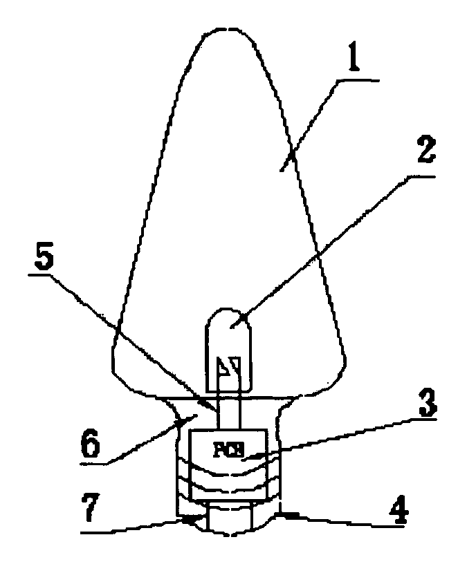
[0007] The present invention provides a new LED design for C7 and C9 bulbs. The PCB electronic circuit board structure enables LEDs to be directly powered by 110-120V AC power supply, and dramatically reduces power consumption compared to traditional C7 and C9 bulbs.

[0008] As shown in FIG. 1, the LED bulb consists of a lamp cover, LEDs, a PCB electronic circuit board, and a brass base or a base made with appropriate material. Different from the traditional bulbs, the bulb of the invention houses the LEDs that are soldered on the PCB board, and the PCB board is embedded inside of the base such that the lamp cover, the LEDs, PCB board, and the base, when fully assembled, forms the invented LED bulb. The PCB board is used here to provide a connection between the internal LEDs and the external 110-120V AC voltage.

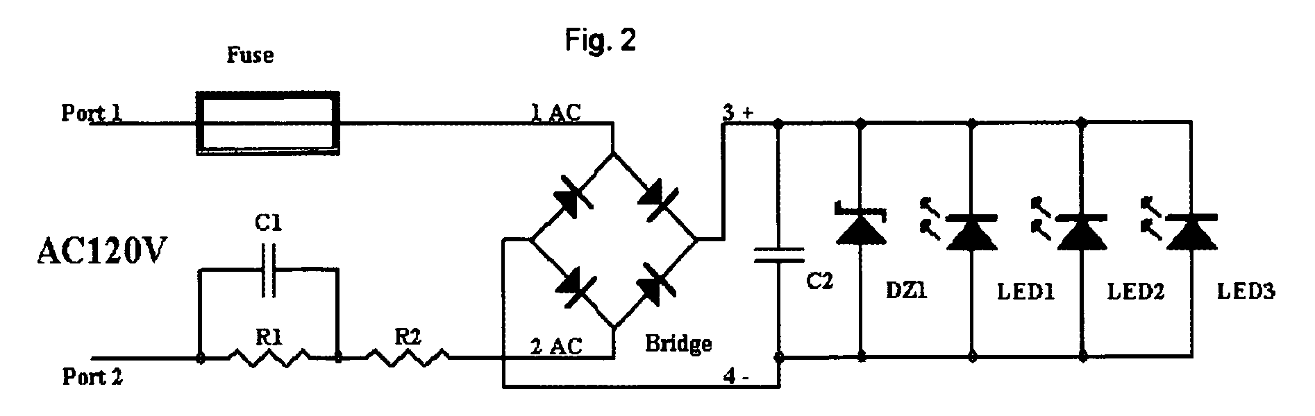
[0009]FIG. 2 shows the electronic circuit of the PCB board used in the LED bulb. After passing through a capacitor C1 and resistors R1 and R2 (C1 is in parallel with R1, and ...


PUM


Abstract

The invention presents a new design of C7 or C9 type LED bulb and its embedded PCB electronic circuit board structure, comprising a lamp cover, LEDs, a PCB circuit board and a base. The bulb houses one or multiple number of LEDs. The LEDs are soldered on the PCB board that is embedded inside of the base. The PCB board power input ports connect to the brass base or are directly wired to outside the base. The base and the lamp cover may be attached together by means of bonding (thermal, sonic or solvent), friction interference fit, adhesive or simply by screwing the lamp cover into the threaded base. The PCB board, utilizing a bridge design, allows the LED bulb to be directly powered by 110-120V AC voltage power sources. The simple bulb design significantly reduces the weight of the entire product and power consumption.

Description

FIELD OF THE INVENTION [0001] The present invention relates to lighting decoration technologies and, more particularly, to light emitting diode (LED) C7 and C9 types bulbs used for lighting and decoration. DESCRIPTION OF RELATED ART [0002] Lighting is one of the most important parts of our everyday life. The light bulbs, since invented in 1879, have profoundly changed human existence by illuminating the night and making it hospitable to a wide range of activity. One of the goals of developing lighting technologies is to meet different illumination requirements for different activities, e.g., Living, office, meeting, entertainment, and etc. An efficient lighting structure not only comforts our eyes, but also save electrical power. The second goal of lighting is to decorate the lighted room by shining on the indoor objects and showing their shapes and sizes. For displaying art works, such as pictures, carpets and flowers, lighting is even required to show their colors inside of a room...

Claims


Application Information

Patent Timeline
IPC IPC(8): F21V15/00
CPCF21Y2101/02H05B33/0803H05B33/0809F21V3/02F21K9/135F21W2121/00Y10S362/80Y02B20/348F21K9/232F21Y2115/10Y02B20/30H05B45/34
Inventor YU, JING JING
Owner YU JING JING
Why Eureka
Try Eureka