Control of engine intake door

a technology for controlling the intake door and the engine, which is applied in the direction of machines/engines, combustion-air/fuel-air treatment, liquid fuel engines, etc., and can solve the problems of increasing the vulnerability to damage from small foreign particles, premature wear of engine components, and increasing maintenance costs

Active Publication Date: 2007-02-01
DONALDSON CO INC
View PDF27 Cites 42 Cited by
  • Summary
  • Abstract
  • Description
  • Claims
  • Application Information

AI Technical Summary

Benefits of technology

[0006] In another aspect, an air induction system of this invention is for an engine having a power activated door for controlling flow of intake air. The system comprises a housing having a hollow interior and an opening in the housing comprising an entryway for receiving intake air into the housing. The door is pivotable between a closed position wherein the opening is closed and an open position wherein intake air may en

Problems solved by technology

The compressor and turbine are designed with small clearances between moving parts which maximize efficiency, but which also increase vulnerability to damage from small foreign particles.
Contamination of intake air, even in a small amount, causes premature wear on engine components, increases maintenance costs, and degrades operational performance and reliability.
Unfortunately, aircraft are exposed to contaminants when operating at low altitudes where air is fre

Method used


Image

  • Control of engine intake door
  • Control of engine intake door
  • Control of engine intake door

Examples


Embodiment Construction

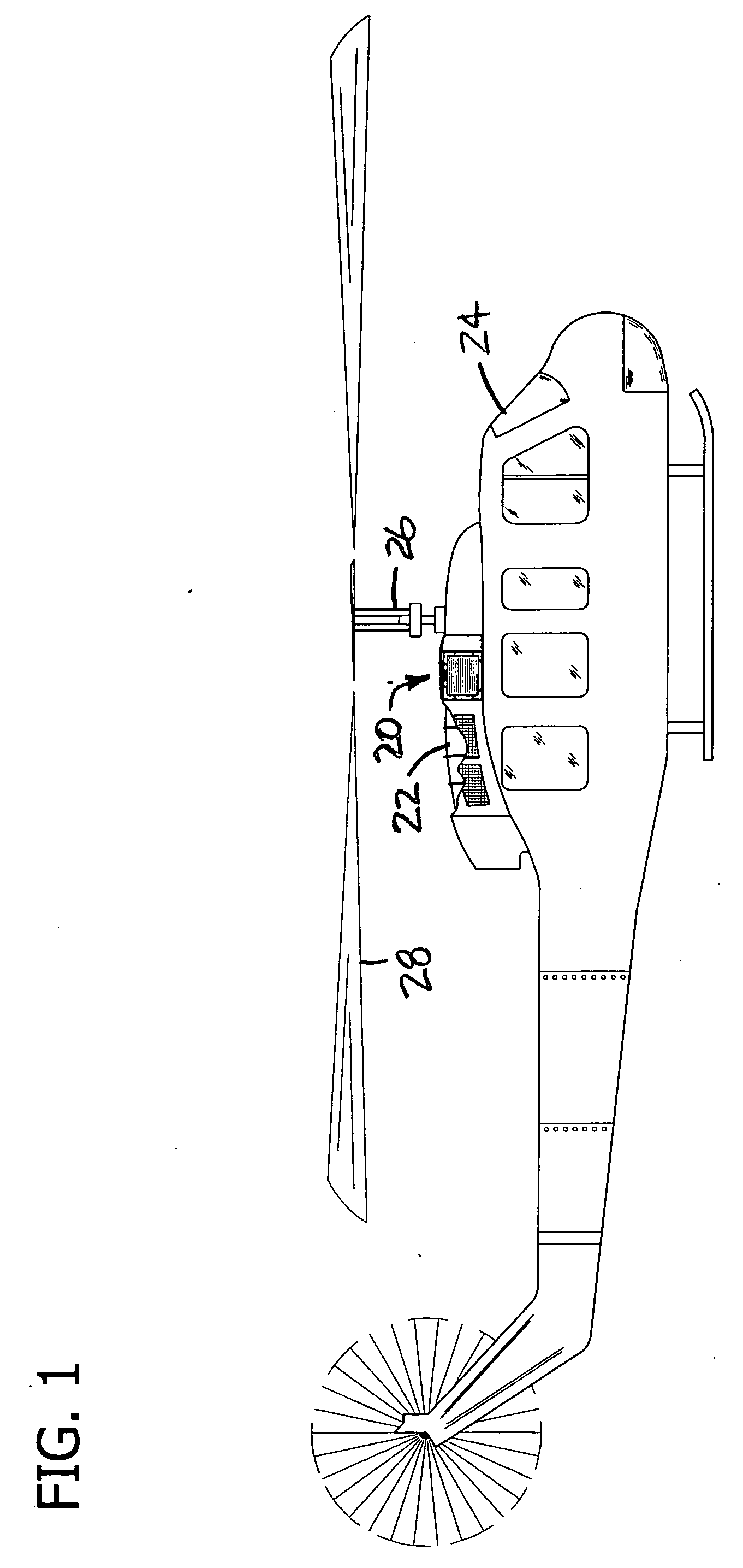
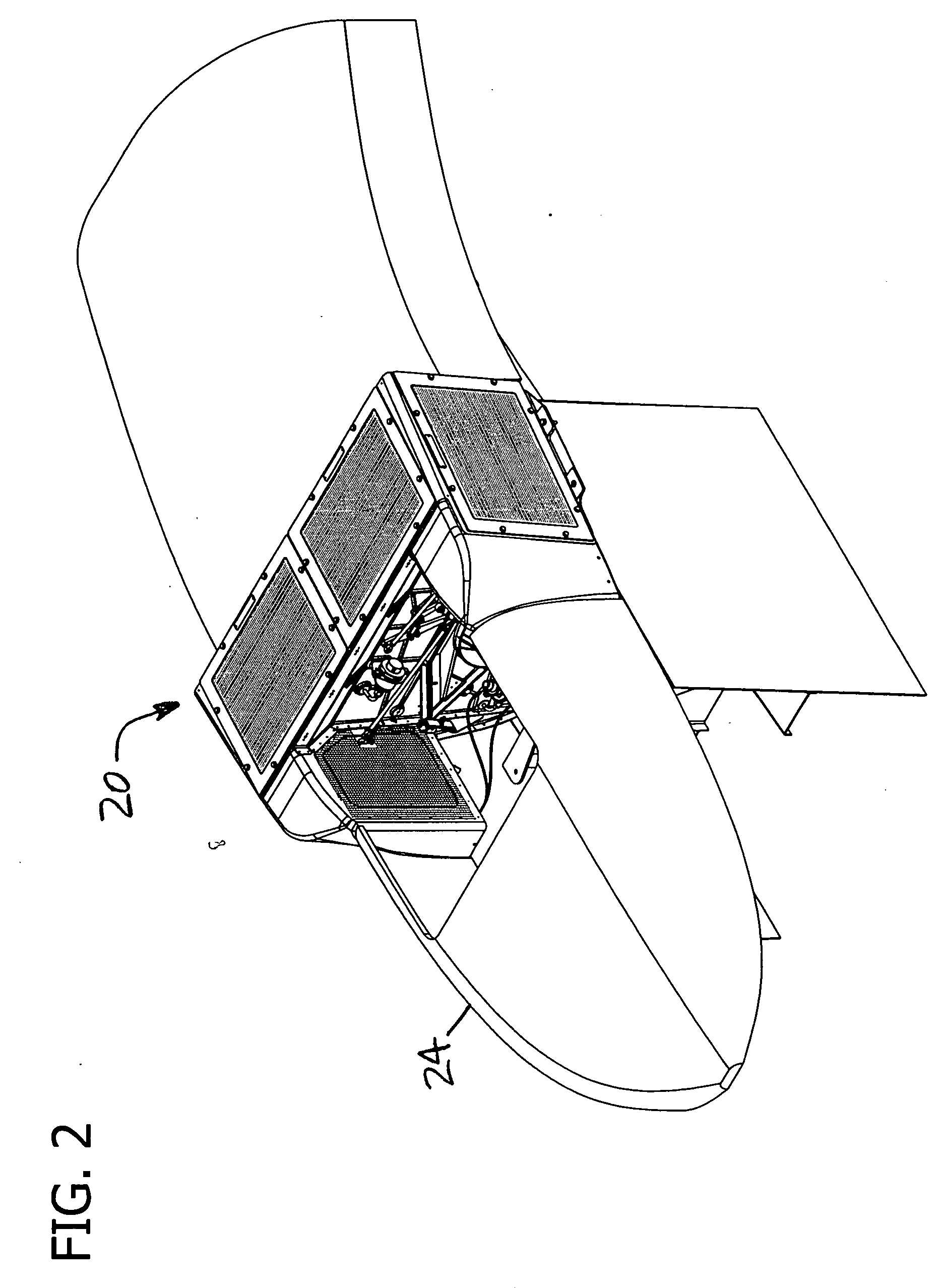
[0021] Referring now to the drawings and in particular to FIGS. 1-3, an air induction system of the present invention is designated generally by 20. The system 20 is configured to receive intake air, remove contaminants from the intake air, and channel intake air to an engine 22 for ingestion by the engine. The system is primarily intended for use with a gas turbine engine which is installed in an aircraft such as a helicopter 24, more particularly as shown a Bell 205 helicopter. However, it is understood that the system can be used with other types of engines or equipment for various applications without departing from the scope of this invention. In the embodiment shown in FIGS. 1 and 2, the system 20 is positioned along the upper fuselage of the helicopter 24, immediately aft of a mast 26 of a rotor 28.

[0022] The air induction system 20 includes a housing, generally designated 30 (FIG. 3), which mounts barrier filter panels 32 each having a porous filter media. The housing has a...


PUM


Abstract

An air induction system for an engine having an improved mechanism for control of an intake door. The system includes a housing having an opening for receiving intake air. A power activated door is pivotable between a closed position wherein the opening is closed and an open position wherein intake air may enter through the opening. Linkages operatively connect an actuator cylinder to the door. The linkages are configured such that movement of the cylinder produces a corresponding rotation of the door which is non-uniform across the cylinder's range of motion. The linkages include first and second bellcranks mounted for pivotal motion, and a link which interconnects the bellcranks. Movement of the cylinder at a first position causes pivoting of the door, while movement at a second position causes substantially no pivoting of the door.

Description

BACKGROUND OF THE INVENTION [0001] This invention relates generally to air intakes for engines, and in particular to an air induction system having an improved mechanism for control of one or more intake doors. [0002] An engine for aircraft propulsion requires intake air that is free from contaminants to provide for efficient combustion and avoid internal damage. The compressor and turbine are designed with small clearances between moving parts which maximize efficiency, but which also increase vulnerability to damage from small foreign particles. Contamination of intake air, even in a small amount, causes premature wear on engine components, increases maintenance costs, and degrades operational performance and reliability. Unfortunately, aircraft are exposed to contaminants when operating at low altitudes where air is frequently contaminated with material from the ground, such as sand and dust. That problem is aggravated for helicopters due to rotor downwash and prolonged low-altit...

Claims


Application Information

Patent Timeline
IPC IPC(8): F02G3/00B64D33/02F04D29/70
CPCB64D33/02F02C7/05F02C7/047B64D2033/0246Y10T137/0536
Inventor STELZER, JAMES F.
Owner DONALDSON CO INC
Why Eureka
Try Eureka