Battery module

a battery module and battery technology, applied in the field of batteries, can solve the problems of unit batteries applying stress to the end plates, deformation of the end plates, and the connection member may become unstably coupled from the end plates, and achieve the effect of enhancing the resistance to bending

Inactive Publication Date: 2007-02-01
SAMSUNG SDI CO LTD
View PDF10 Cites 83 Cited by
  • Summary
  • Abstract
  • Description
  • Claims
  • Application Information

AI Technical Summary

Benefits of technology

[0011] The present invention provides a battery module including end plates having an enhanced resistance to bending.
[0012] According to one exemplary embodiment of the present invention, a battery module is provided including a plurality of unit batteries arranged in series, an end plate located at each end of the plurality of unit batteries, a plurality of connecting members connected to each end plate to fix the end plates to the plurality of unit batteries, and at least one reinforcing member on each end plate, the at least one reinforcing member enhancing resistance to bending of each end plate.

Problems solved by technology

However, when the battery module is used for a long time, swelling occurs in the unit batteries causing the unit batteries to apply stress to the end plates.
As a result, the end plates may be deformed and the connecting member may become unstably coupled from the end plates.
Stress may become concentrated on the unstable coupling portion between the end plates and the connecting members, causing damage to the unstable coupling portion.
However, a thicker connecting member results in an increase in the weight of the battery module, thus deteriorating the performance of the device powered by the battery module.

Method used


Image

  • Battery module
  • Battery module
  • Battery module

Examples


Embodiment Construction

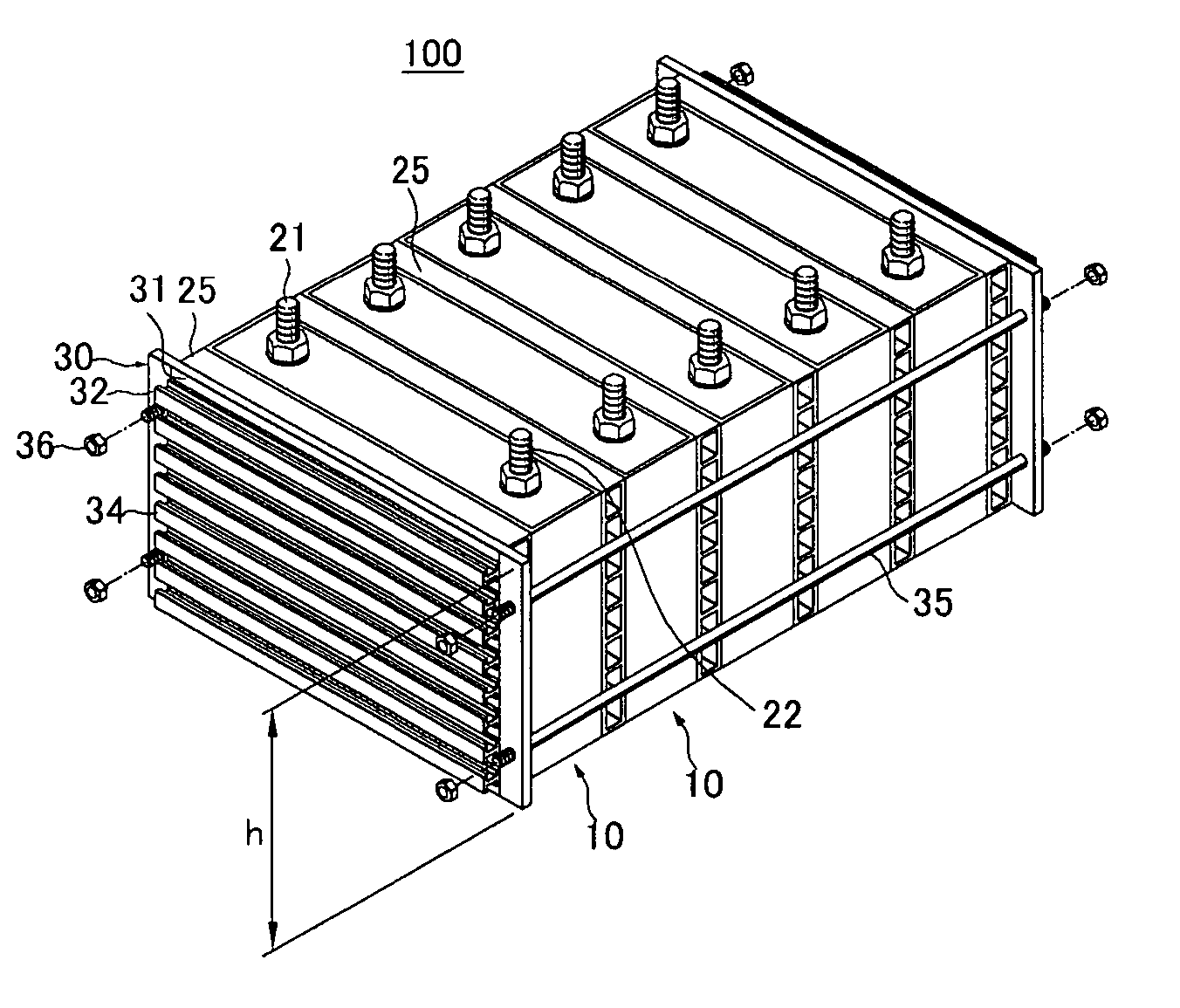
[0030] Referring to FIGS. 1 and 2, a battery module 100 of the present embodiment includes a plurality of unit batteries 10 and a plurality of barriers 25 disposed adjacent each planar surface of the unit batteries to provide coolant passages.

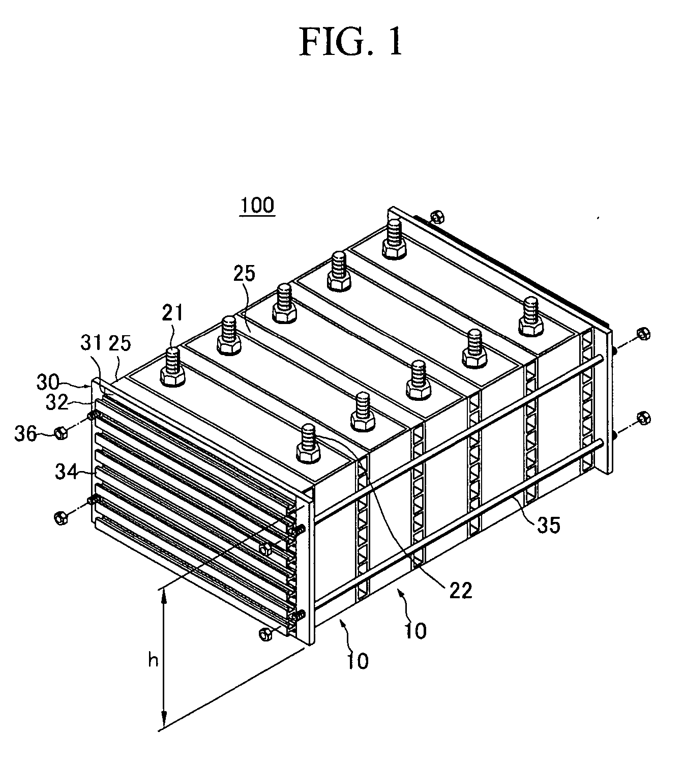
[0031] End plates 30 are installed adjacent each end unit battery to bookend the unit batteries 10 of the battery module 100. Each end plate 30 includes a contact portion 31 contacting a corresponding adjacent barrier 25 and extending portions 32 extending from the contact portion 31.

[0032] In one exemplary embodiment, a height of each extending portion 32 is identical to a height “h” of the contacting portion 31. However, the present invention is not limited to this case.

[0033] The end plates 30 are connected to each other by connecting members 35, such as restraint rods, to fix the unit batteries 10 and the barriers 25. In one exemplary embodiment, two connecting members 35 are installed on each extending portion 32 of each end plate 30. T...


PUM

PropertyMeasurementUnit
resistanceaaaaaaaaaa
heightaaaaaaaaaa
energy densityaaaaaaaaaa

Abstract

A battery module including a plurality of unit batteries arranged in series, an end plate located at each end of the plurality of unit batteries, a plurality of connecting members connected to each end plate to fix the end plates to the unit batteries, and at least one reinforcing member on each end plate, the reinforcing member serving to enhance the resistance to bending of each end plate.

Description

CROSS-REFERENCES TO RELATED APPLICATIONS [0001] This application claims priority to and the benefit of Korean Patent Application Nos. 10-2005-0069442 and 10-2005-0069482 filed on Jul. 29, 2005, both applications filed in the Korean Intellectual Property Office, the entire content of which are incorporated herein by reference. BACKGROUND OF THE INVENTION [0002] 1. Field of the Invention [0003] The present invention relates to a battery module having end plates with increased resistance to bending. [0004] 2. Description of the Related Art [0005] Recently, a high output rechargeable battery (“unit battery”) using nonaqueous electrolyte and having a high energy density has been developed. High capacity batteries are used as the power source for driving motors, such as those of hybrid electric vehicles. [0006] A high capacity secondary battery (“battery module”) is composed of a plurality of unit batteries. The unit battery includes an electrode assembly having positive and negative elec...

Claims


Application Information

Patent Timeline
Patent Type & Authority Applications(United States)
IPC IPC(8): H01M2/24H01M50/529H01M50/209H01M50/264
CPCH01M2/24H01M2/1077Y02E60/10H01M50/529H01M50/209H01M50/264
Inventor JEON, YOON-CHEOLKIM, TAE-YONG
Owner SAMSUNG SDI CO LTD
Why Eureka
Try Eureka