Multipolar, virtual-electrode catheter with at least one surface electrode and method for ablation
a virtual electrode and electrode technology, applied in the field of virtual electrode electrode catheters, can solve the problems of increasing the depth of the lesion, requiring high power, and increasing the temperature at the electrode-tissue interface, so as to improve the efficiency of ablation
- Summary
- Abstract
- Description
- Claims
- Application Information
AI Technical Summary
Problems solved by technology
Method used
Image
Examples
first embodiment
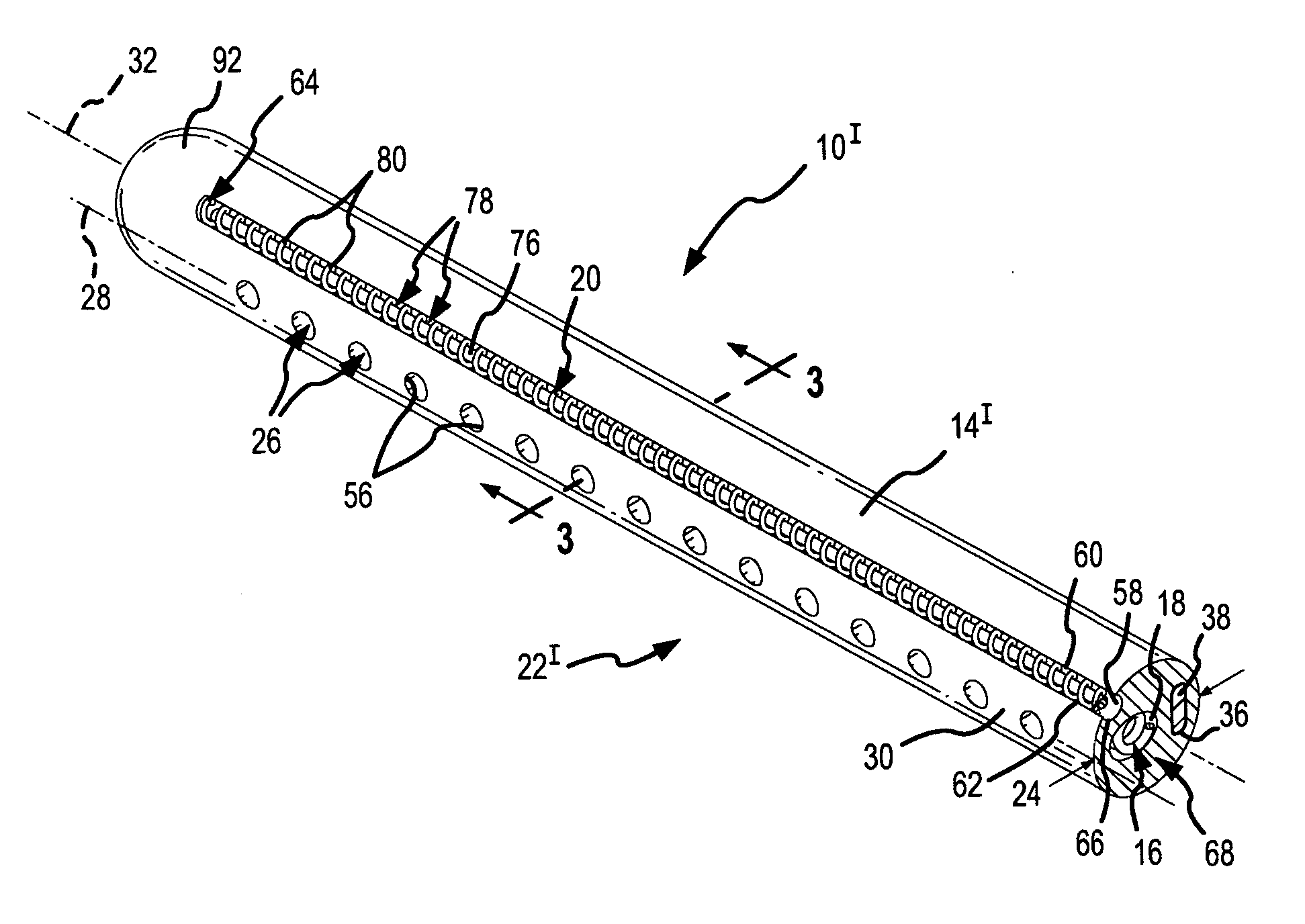
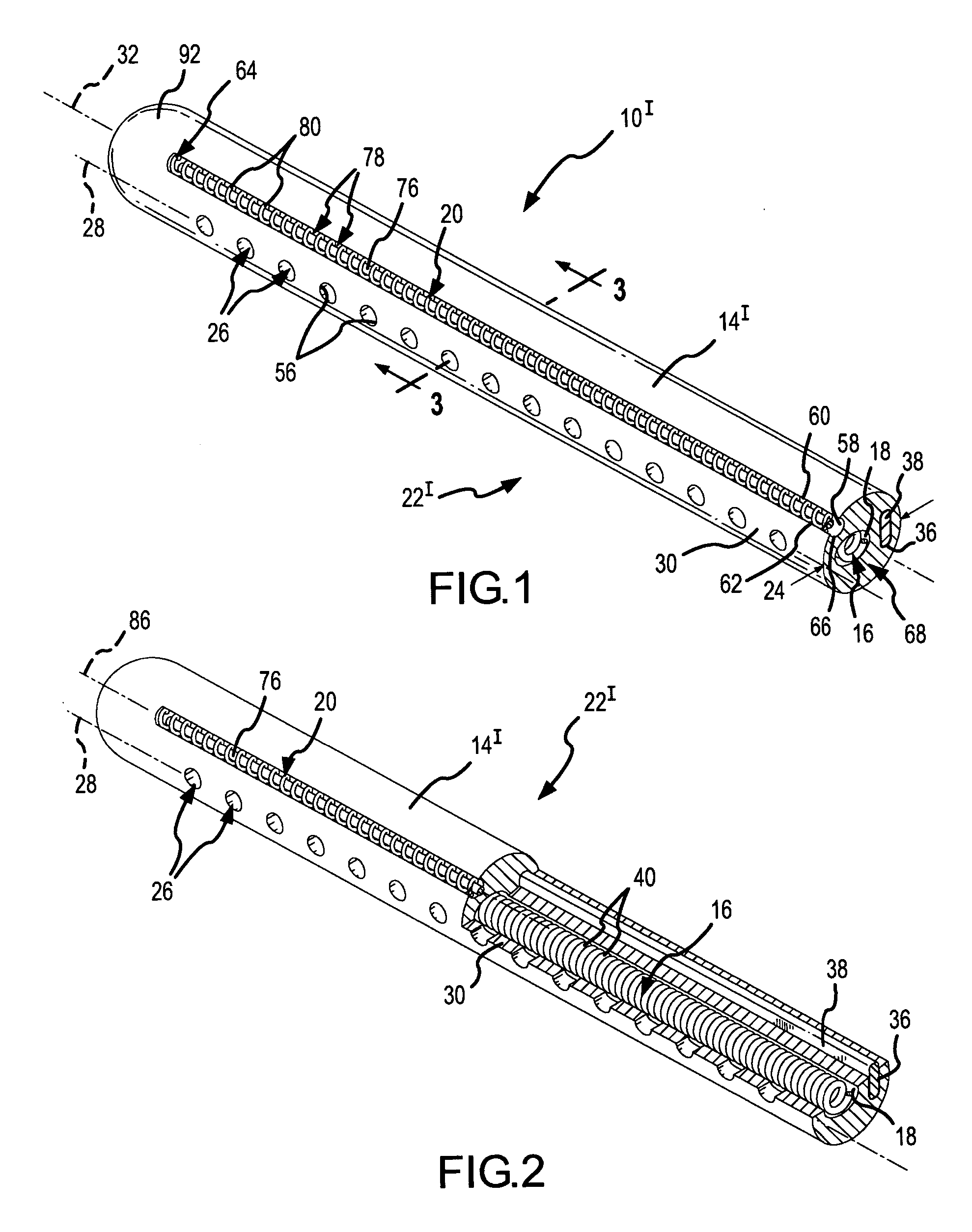
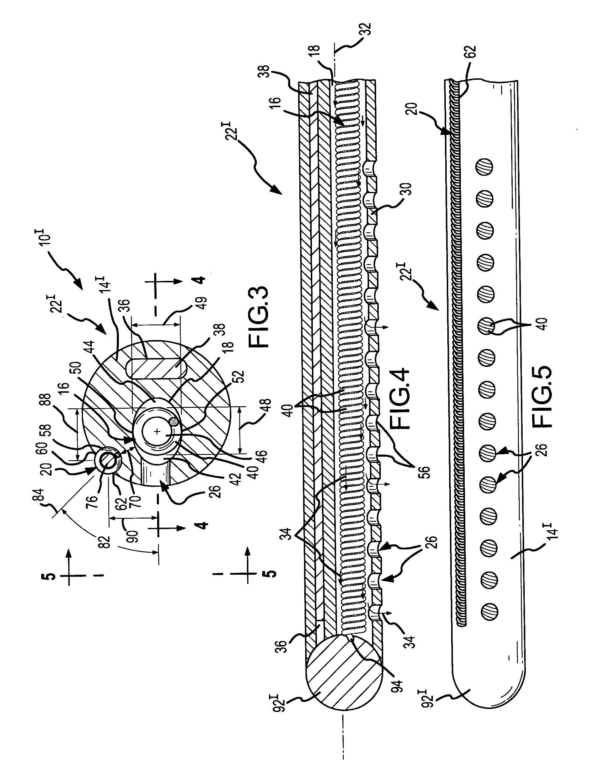
[0042] As shown in FIGS. 1, 2, 4, and 5, an exit feature extends through a sidewall 30 of the catheter body 14I. In particular, the exit feature in this first embodiment comprises a plurality of exit portholes or nozzles 26 that are arranged along a longitudinally-extending porthole centerline 28 along the surface of the catheter body 14I. As best seen by looking at FIGS. 3 and 4, these exit portholes 26 extend through the sidewall 30 of the catheter body 14I. In the depicted embodiment, as shown to good advantage in FIGS. 3 and 4, the exit portholes 26 extend radially through the sidewall 30 relative to a catheter longitudinal axis 32.
[0043] The catheter body 14I includes at least one longitudinally-extending internal lumen 18 in which an internal flexible current carrier or conductor 16 is mounted. If desirable, more than one elliptical internal lumen may be present. In the embodiment depicted in FIGS. 1-5, the internal lumen 18 has an elliptical cross section, which, among other ...
fourth embodiment
[0062]FIG. 10 is a cross-sectional view similar to FIGS. 3, 6, and 9, but depicts a distal portion 22IV of a fourth embodiment 10IV of the present invention. The fourth embodiment 10IV is most similar to the second embodiment 10II, but the large internal coil 16 has again been replaced by a small internal coil 102. This fourth embodiment comprises an exit slot 96 like the exit slot depicted in the embodiment of FIGS. 6-8.
[0063]FIGS. 11-13 depict a distal portion 22V of a bipolar, virtual-electrode catheter 10V according to a fifth embodiment of the present invention. FIG. 11 is similar to FIG. 1. In the fifth embodiment 10V, however, the surface electrode is a thermally and electrically conductive tube 106 rather than a coil 20 (FIG. 1). This surface electrode tube 106 may be metal, or may be constructed from some other conductive material (e.g., conductive silicone carbide or conductive polymer). For example, the surface electrode tube 106 depicted in FIGS. 11-13 may be a NiTi meta...
sixth embodiment
[0068] As suggested by FIG. 16, which is a cross-sectional view of a bipolar, virtual-electrode catheter 10VI taken along line 16-16 of FIG. 15, this embodiment may use two fluid sources (not shown). For example, a first saline source may supply cooling fluid 110 to the surface electrode tube 108, and a second fluid source may provide conductive fluid 34 (see e.g., FIG. 4) to the elliptical internal lumen 18 in which the large internal coil 16 depicted in FIGS. 14-16 resides. The exit port 112 shown in FIGS. 14 and 16 may be somewhat constricted to control the rate of flow through the surface electrode tube 108. Since it is possible that the ablative energy (e.g., RF energy) being delivered to the conductive fluid 34 that ultimately departs the exit portholes 26 may reach the fluid 110 flowing through the exit port 112 of the surface electrode tube 18, having two separate fluid supply systems is desirable. In order to control the total amount of saline delivered into the patient's ...
PUM
 Abstract
Description
Claims
Application Information
 - R&D
- Intellectual Property
- Life Sciences
- Materials
- Tech Scout
- Unparalleled Data Quality
- Higher Quality Content
- 60% Fewer Hallucinations
Browse by: Latest US Patents, China's latest patents, Technical Efficacy Thesaurus, Application Domain, Technology Topic, Popular Technical Reports.
© 2025 PatSnap. All rights reserved.Legal|Privacy policy|Modern Slavery Act Transparency Statement|Sitemap|About US| Contact US: help@patsnap.com


