Drive over mower deck

a mower and drive technology, applied in the field of mowers and utility vehicles, can solve the problems of difficult reinstallation, difficulty in reinstallation, and difficulty in removing mower decks from tractor or vehicle, and achieve the effect of quick and easy mounting or removal and preventing damage to caster wheels

Active Publication Date: 2007-02-08
DEERE & CO
View PDF12 Cites 26 Cited by
  • Summary
  • Abstract
  • Description
  • Claims
  • Application Information

AI Technical Summary

Benefits of technology

[0007] The invention provides a drive over mower deck that can be quickly and easily mounted or removed from a tractor between the tractor's front and rear wheels. To drive over the mid-mounted mower deck, the deck may be lowered to a position flat on the ground. This is done to prevent damage of caster wheels, brackets other related components that cannot bear the additional weight of the tractor or vehicle during the drive over procedure. The working components of the deck are protected by a drive over belt shield from the weight of the tractor or vehicle applied when the front or rear tires drive over the deck.
[0008] The invention also provides a mechanism for lowering a mower deck to the drive over position lying flat on the ground, as well as raising the mower deck to a cutting height. The mechanism includes a pin that sets the gauge wheel height that may be operated using a cam lever. The invention also may provide a lift system that allows connection to a drive over mower deck with minimal manipulation of the mower deck by the operator.

Problems solved by technology

These types of mower decks are difficult to remove from the tractor or vehicle due to the high weight of the deck and the proximity of the deck to tires and other parts of the tractor or vehicle.
When the operator is ready to use the mower deck again, reinstallation may be more difficult than removal of the mower deck.
The difficulty of reinstallation may be due at least in part to the heavy weight of the deck, the resistance of the gauge wheels supporting the deck to lateral movement, obstructions under the tractor such as a front wheel drive shaft, and irregular ground surfaces.

Method used


Image

  • Drive over mower deck
  • Drive over mower deck
  • Drive over mower deck

Examples


Embodiment Construction

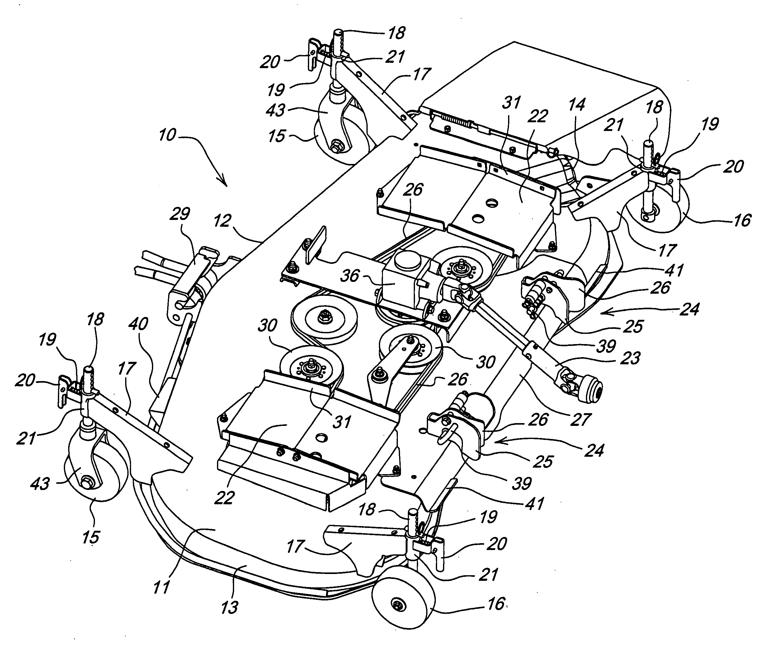
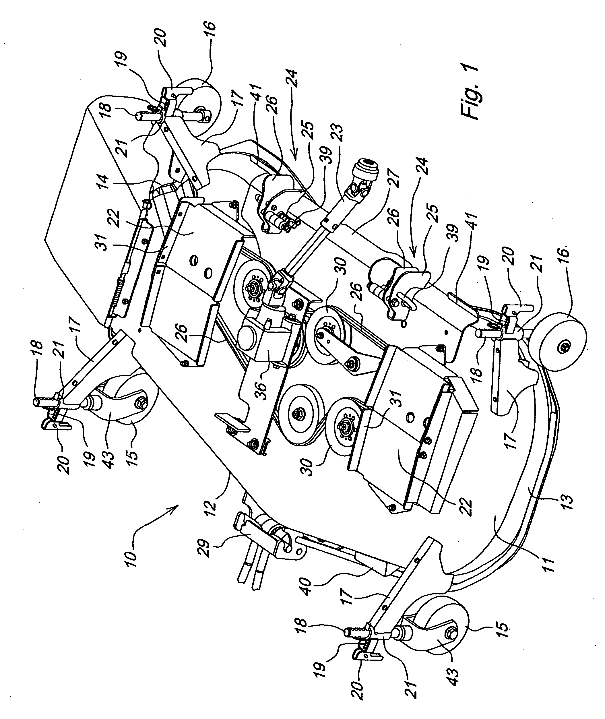
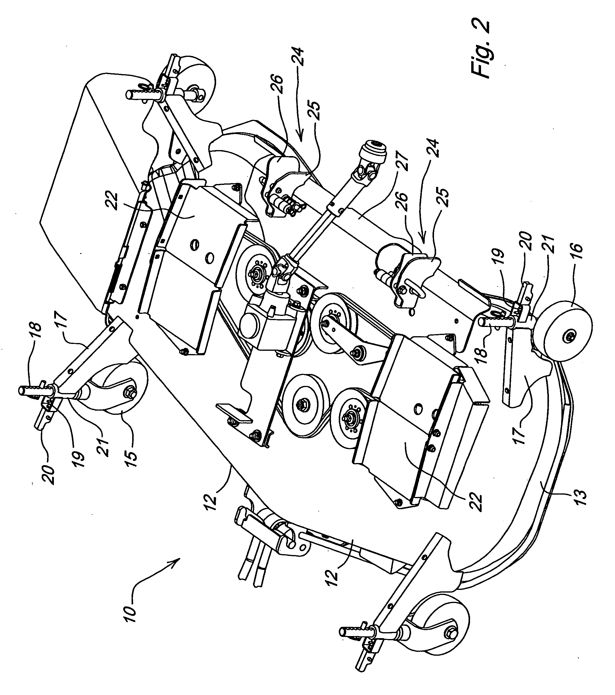
[0013] As shown in FIGS. 1 and 2, in one embodiment, drive over mower deck 10 may cover a plurality of rotary cutting blades, and preferably three cutting blades, mounted on the lower ends of vertically oriented spindles. Alternatively, the drive over mower deck may cover two cutting blades, or more than three cutting blades. The drive over mower deck may have a top surface 11, a front facing edge 12 with a rim, left and right side edges 13, 14, and a back edge 27. The drive over mower deck may have a total width greater than the track width of at least one set of wheels of a tractor or utility vehicle, and may be mid-mounted under the tractor or vehicle frame between the front and rear wheels.

[0014] In one embodiment, drive over mower deck 10 may have a first pair of gauge wheels 15 mounted adjacent the front edge of the deck, and a second pair of gauge wheels 16 mounted adjacent the rear edge of the deck. In a cutting position, as shown in FIG. 1, the mower deck may be at least p...


PUM


Abstract

A drive over mower deck has a top surface with downwardly depending surfaces defining a front edge, a back edge, and left and right side edges, at least one belt shield over the top surface, a first pair of gauge wheels mounted adjacent the front edge the deck, and a second pair of gauge wheels mounted adjacent the back edge of the deck. Each pair of gauge wheels is movable vertically to at least one position above the ground surface such that the mower deck is supported by the front edge, back edge, and left and right side edge. Each gauge wheel being releasably lockable at a plurality of different positions.

Description

FIELD OF THE INVENTION [0001] This invention relates generally to tractors and utility vehicles used for agricultural work and lawn care, and particularly to mower decks carried by such tractors or vehicles that cover rotary cutting blades. More specifically, the invention relates to a drive over mower deck that may be easily attached and removed from a tractor or vehicle. BACKGROUND OF THE INVENTION [0002] Tractors and utility vehicles used for agricultural work and lawn care may carry a mid-mounted mower deck covering two or more rotary cutting blades on the lower ends of vertically oriented spindles. A mower deck may be attached to a tractor or other vehicle with mechanical linkages that allow the deck to be carried at a range of different cutting heights, and raised or lowered between each height. The blade spindles may be rotated by one or more belts and pulleys above the surface of the deck, which may be driven by an engine and / or power take off shaft. The deck perimeter may h...

Claims


Application Information

Patent Timeline
Patent Type & Authority Applications(United States)
IPC IPC(8): A01D34/00
CPCA01D34/64
Inventor CLEMENT, BRIAN RICHARDDEVES, THOMAS JOHNFOX, ROBERT NEILTREFZ, HARLIN JAMES
Owner DEERE & CO
Why Eureka
Try Eureka