Catalyst module overheating detection and methods of response

a technology of catalytic modules and detection methods, applied in the direction of combustion types, instruments, combustion using catalytic materials, etc., can solve the problems of thermal damage to the catalytic module, lack of uniformity, narrow operating range of systems, etc., and achieve the effect of reducing temperatur

Inactive Publication Date: 2007-02-08
KAWASAKI HEAVY IND LTD
View PDF87 Cites 26 Cited by
  • Summary
  • Abstract
  • Description
  • Claims
  • Application Information

AI Technical Summary

Problems solved by technology

Unfortunately, however, such systems generally have a narrower operating range than conventional diffusion flame or lean premix combustors.
For example, operation of catalytic combustors above desired temperature limits, which may vary depending on the particular application and design of each combustor system, may result in thermal damage to the catalytic module.
Such operation could be a result of a variety of contributing factors in single or multi-combustor applications, including variations in fuel composition outside of specifications, blockage of catalytic channels caused by foreign objects, lack of uniformity of inlet fuel-air mixture, flameholding in the burn-out-zone radiating heat back to the catalyst, or lack of uniformity of catalytic material on the substrate due to manufacturing variability.
In multi-combustor specific applications discussed below, operation above desired temperature limits may be a result of combustor-to-combustor non-uniformities.
The application of industrial, or otherwise, gas turbine engines with catalytic combustion, however, has been limited to the single-silo configuration.
The application of catalytic combustion in a multi-combustor configuration poses several additional problems that may lead to thermal damage to one or more catalyst modules.

Method used


Image

  • Catalyst module overheating detection and methods of response
  • Catalyst module overheating detection and methods of response
  • Catalyst module overheating detection and methods of response

Examples


Embodiment Construction

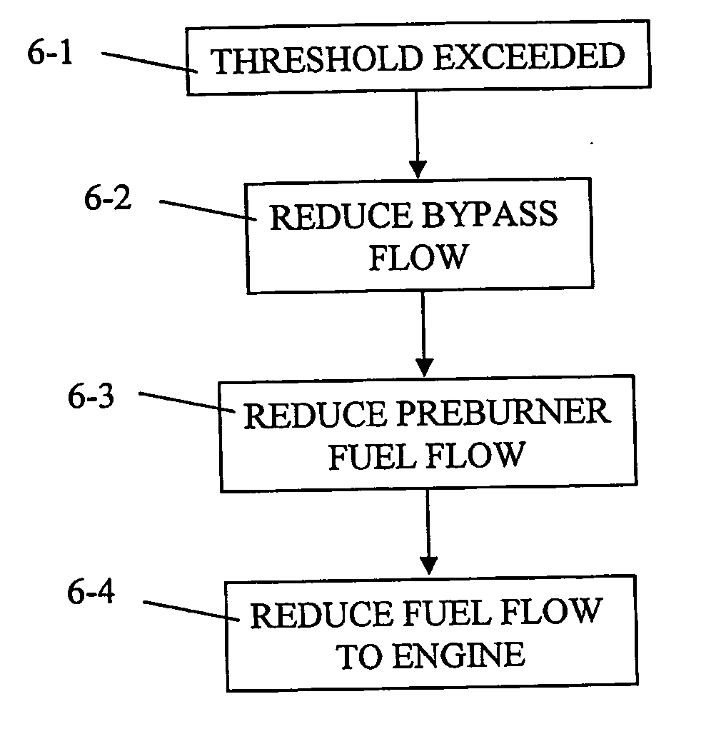
[0020] The present invention provides various methods of operating catalytic combustion systems including detecting, responding to, and preventing catalyst overheating. The following description is presented to enable any person skilled in the art to make and use the invention. Descriptions of specific structures, functions, techniques, and applications are provided only as examples. Various modifications to the examples described herein will be readily apparent to those skilled in the art, and the general principles defined herein may be applied to other examples and applications without departing from the spirit and scope of the invention. Thus, the present invention is not intended to be limited to the examples described and shown, but is to be accorded the scope consistent with the appended claims.

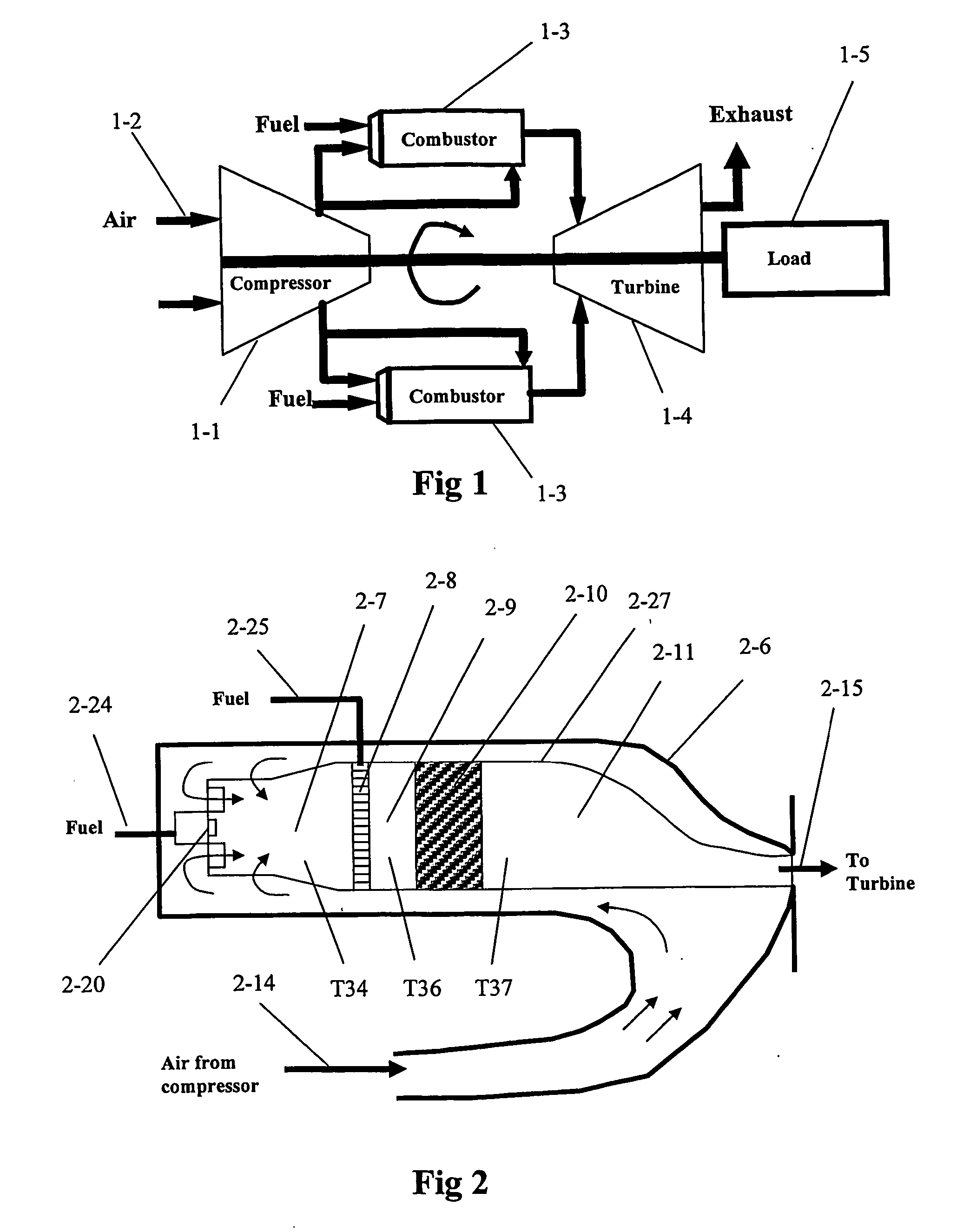
[0021] Exemplary methods and systems are described herein for improved control strategies and efficient application of single or multi-combustor catalytic combustion system or mixed (...


PUM

PropertyMeasurementUnit
temperaturesaaaaaaaaaa
temperatureaaaaaaaaaa
outlet gas temperatureaaaaaaaaaa

Abstract

According to one aspect, a method of detecting catalyst module overheating in a catalytic combustion system is provided. In one example, the method includes detecting one or more signals from at least one probe adapted to obtain values associated with at least one of the outlet gas temperature of a catalyst module and the outlet face temperature of the catalyst module included in a catalytic combustor. The one or more signals are compared with a preselected value associated with catalyst overheating. The detected temperature may be detected over time to determine a rate of change in the temperature. The temperature may be detected with a UV sensor directed to the catalyst outlet face.

Description

BACKGROUND [0001] 1. Field of the Invention [0002] The invention relates generally to catalytic combustion systems and control methods, and more particularly to systems and methods for detecting and responding to catalyst module overheating or conditions that may result in a catalyst module overheating in single or multi-combustor processes as they relate to and are utilized by catalytic gas turbine engines. [0003] 2. Description of the Related Art [0004] In a conventional gas turbine engine, the engine is controlled by monitoring the speed of the engine and adding a proper amount of fuel to control the engine speed. Specifically, should the engine speed decrease, fuel flow is increased causing the engine speed to increase. Similarly, should the engine speed increase, fuel flow is decreased causing the engine speed to decrease. In this case, the engine speed is the control variable or process variable monitored for control. A similar engine control strategy is used when the gas turb...

Claims


Application Information

Patent Timeline
Patent Type & Authority Applications(United States)
IPC IPC(8): F23R3/40G01K
CPCF23C13/04F23C13/06F23N5/082F23N5/102F23R3/40F23N2025/16F23N2025/21F23N2041/20F23R3/34F23N5/242F23N2225/21F23N2225/16F23N2241/20
Inventor JOSHI, AJAYYEE, DAVID
Owner KAWASAKI HEAVY IND LTD
Why Eureka
Try Eureka