Hermetic compressor

Inactive Publication Date: 2007-02-08
SAMSUNG GWANGJU ELECTRONICS CO LTD
View PDF3 Cites 11 Cited by
  • Summary
  • Abstract
  • Description
  • Claims
  • Application Information

AI Technical Summary

Benefits of technology

[0012] Additional aspects and / or advantages of the invention will be set forth in part in the description which follows and, in part, will be obvious from the description, or may be learned by practice of the invention.

Problems solved by technology

However, this is problematic because a decreased amount of gaseous refrigerant is introduced into the cylinder block 12 due to the amount of the introduced oil, resulting in degradation of compression capability.
This results in degradation in operational efficiency of the compressor.

Method used


Image

  • Hermetic compressor
  • Hermetic compressor
  • Hermetic compressor

Examples


Embodiment Construction

[0023] Reference will now be made in detail to a hermetic compressor according to a preferred embodiment of the present invention, examples of which are illustrated in the accompanying drawings, wherein like reference numerals refer to like elements throughout. The embodiment is described below to explain the present invention by referring to the figures.

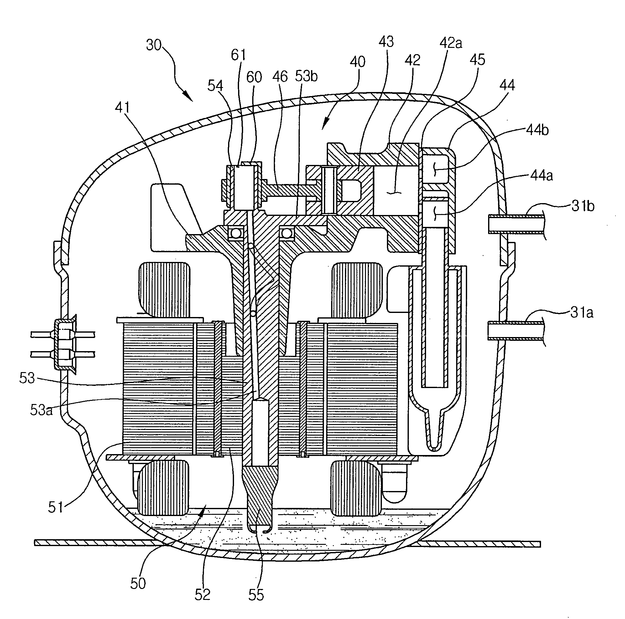
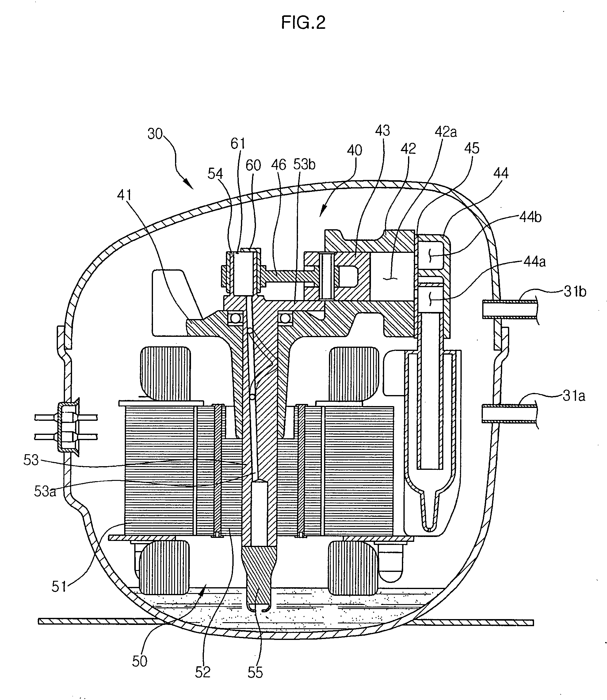
[0024] Referring to FIG. 2, a hermetic compressor according to an embodiment of the present invention is illustrated in sectional view. The hermetic compressor includes a compression unit 40 arranged in a hermetic container 30, which defines a hermetic space therein, to compress a refrigerant, and a drive unit 50 to drive the compression unit 40. The hermetic container 30 is provided at different positions thereof with a suction pipe 31a to introduce a refrigerant from an external station into the hermetic container 30 and a discharge pipe 31b to discharge a compressed refrigerant from the compression unit 40 to outside of the herm...


PUM


Abstract

A hermetic compressor capable of appropriately injecting oil from an eccentric unit of a rotating shaft in accordance with amounts required by respective regions. The hermetic compressor comprises a compression chamber in which a refrigerant is compressed, a piston to compress the refrigerant in the compression chamber, a rotating shaft to provide a drive force to advance or retreat the piston in the compression chamber, the rotating shaft having an oil path formed therein, a hollow eccentric unit to eccentrically rotate as the rotating shaft rotates, a bushing coupled to the eccentric unit and having a closed surface to close an opening of the eccentric unit, and an oil injection port formed at the bushing to determine an injection direction and injection degree of oil injected along an inner peripheral surface of the eccentric unit.

Description

CROSS-REFERENCE TO RELATED APPLICATION [0001] This application claims the benefit of Korean Patent Application No. 2005-72028, filed on Aug. 6, 2005 in the Korean Intellectual Property Office, the disclosure of which is incorporated herein by reference in its entirety. FIELD OF THE INVENTION [0002] The present invention relates to a hermetic compressor, and, more particularly, to a hermetic compressor capable of appropriately injecting oil from an eccentric unit of a rotating shaft in accordance with amounts required by respective regions. BACKGROUND OF THE INVENTION [0003] Referring to FIG. 1, a conventional hermetic compressor is illustrated in sectional view. The hermetic compressor is a device to suction, compress, and discharge a refrigerant under a hermetic atmosphere, and includes a compression unit 10 to compress the refrigerant, and a drive unit 20 to drive the compression unit 10. [0004] The compression unit 10 is arranged in a hermetic container 1 that defines a hermetic ...

Claims


Application Information

Patent Timeline
IPC IPC(8): F01B31/10
CPCF04B39/0253F04B39/0022F04B39/0269F04B39/0246F04B39/023F04B9/045F16C33/04F05B2260/506Y10S417/902
Inventor YOON, YONG TAE
Owner SAMSUNG GWANGJU ELECTRONICS CO LTD
Why Eureka
Try Eureka