Active-passive expansion hook type anchor rod

An active-passive, hook-type technology, applied in the installation of bolts, mining equipment, earthwork drilling and mining, etc., can solve the problems of affecting the anchoring effect and safety, reducing the anchoring effect, disappearing, etc., to achieve the effect of ensuring the anchoring effect and safety

Inactive Publication Date: 2014-07-23
SHANDONG UNIV OF SCI & TECH +1
View PDF7 Cites 0 Cited by
  • Summary
  • Abstract
  • Description
  • Claims
  • Application Information

AI Technical Summary

Problems solved by technology

In this passive expansion method, the countersunk anchor first squeezes the expansion tube, and the expansion tube itself expands to cause friction with the rock and soil body. The expansion of the expansion tube itself consumes energy, which will inevitably reduce the anchoring effect to a certain extent.
Moreover, after the expansion tube is expanded in the passive expansion mode, the direction of the expansion opening of the expansion tube is towards the inner side of the borehole. In this case, if the rock and soil mass is greatly deformed, the extrusion force of the countersunk anchor bolt may be insufficient. or disappear, the friction between the expansion pipe and the rock and soil body will also be insufficient or disappear
Moreover, the mode of action between the expansion pipe and the rock and soil mass has no other mode of action except friction
Therefore, when the above situation occurs, the entire anchor rod can be taken out from the borehole, and the anchoring effect is completely lost, which seriously affects the anchoring effect and safety.

Method used


Image

  • Active-passive expansion hook type anchor rod
  • Active-passive expansion hook type anchor rod
  • Active-passive expansion hook type anchor rod

Examples


Embodiment Construction

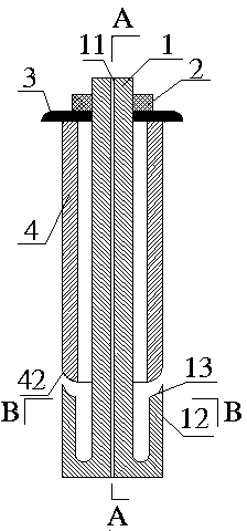
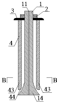
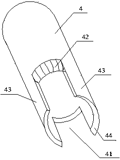
[0015] According to the drawings, the casing body 4 of the present invention is set on the outside of the rod body 1, and a tray 3 and a nut 2 are arranged on the head, and the tray 3 can transmit the tightening force of the nut 2 to the casing body 4 and the rock and soil around the borehole. , the nut 2 is connected to the rod body 1 through threads, and the rod body 1 will move toward the nut 2 relative to the casing body 4 during the tightening process of the nut 2 . Two casing notches 41 and two passive expansion fins 43 are provided at the tail of the casing body 4, the depth of the casing notch 41 is consistent with the length of the passive expansion fins 43, and the bottom of the casing notch 41 is at the bottom of the casing. The outer side of the main body 4 is provided with an active expansion support arc 42 , and the inner side of the tail of the passive expansion wing 43 is provided with a passive expansion wing arc 44 . The tail of the rod body 1 is provided wit...


PUM


Abstract

The invention provides an active-passive expansion hook type anchor rod. A sleeve body is arranged outside a rod body in a sleeved mode, the head of the sleeve body is provided with a tray and a nut, the tray can transmit nut tightening force to the sleeve body and a rock-soil body around a drill hole, the nut is connected with the rod body through threads, and in the process of tightening the nut, the rod body will move toward the nut relative to the sleeve body. The tail of the sleeve body is provided with two sleeve notches and two passive expansion fins, the depth of the sleeve notches is consistent with the length of the passive expansion fins, the positions, located on the outer side of the sleeve body, of the bottoms of the sleeve notches are provided with active expansion supporting arcs, and a passive expansion fin arc is arranged on the inner side of the tail of each passive expansion fin. Two active expansion hooks and two passive expansion heads are arranged at the tail of the rod body, an active expansion hook arc is arranged on the inner side of the head of each active expansion hook, the active expansion hooks are consistent with the sleeve notches in arc length and radian, the radian and the maximum arc length of the passive expansion heads are consistent with the radian and the arc length of the passive expansion fins. The rod body and the sleeve body are sleeved together, before tightening the nut, the sleeve notches are just filled with the active expansion hooks, and the passive expansion heads make contact with the passive expansion fin arcs.

Description

Technical field [0001] The patent of the present invention relates to a support arrangement for rock and soil mass, in particular to an active and passive expansion hook anchor rod. Background technique [0002] With the construction of more and more underground projects, its support is particularly important, and the bolt is used as a commonly used support device because of its good support effect and economical applicability. [0003] In order to increase the contact force between the anchor and the rock-soil body and improve the support effect, various expansive anchors have emerged as the times require, but most of the expansive anchors are passively expanded, that is, when the expansion pipe moves outward due to the countersunk anchor bolt It is squeezed and expanded to cause friction with rock and soil, so as to achieve the anchoring effect. For example, the publication number is: CN 103103989 A, and the publication date is 2013.5.15 the end expansion type recoverable...

Claims


Application Information

Patent Timeline
Patent Type & Authority Applications(China)
IPC IPC(8): E21D21/00
Inventor 贾宏俊李志国尹发利
Owner SHANDONG UNIV OF SCI & TECH
Why Eureka
Try Eureka