Intake device and mounting structure of valve unit

a technology of valve unit and mounting structure, which is applied in the direction of air intake for fuel, machines/engines, combustion air/fuel air treatment, etc., can solve the problems of deteriorating engine performance, affecting the performance of the engine, and the valve member is likely to leak through the gap, so as to reduce the displacement of the axes of the valve member among the plural valve units , the effect of not increasing the torque of the sha

Inactive Publication Date: 2007-02-08
DENSO CORP
View PDF4 Cites 22 Cited by
  • Summary
  • Abstract
  • Description
  • Claims
  • Application Information

AI Technical Summary

Benefits of technology

[0011] In this case, dimensional tolerances between the plural valve units and the intake manifold are reduced by the deformation of the deformed members. Further, displacement of the axes of the valve members among the plural valve units is reduced. Because positions of the axes of the plural valve members substantially coincide in the intake manifold, torque o...

Problems solved by technology

Therefore, gaps exist between the valve member and the housing and between the housing and the intake manifold.
As a result, even when the valve member is operated to a position to close the p...

Method used


Image

  • Intake device and mounting structure of valve unit
  • Intake device and mounting structure of valve unit
  • Intake device and mounting structure of valve unit

Examples


first example embodiment

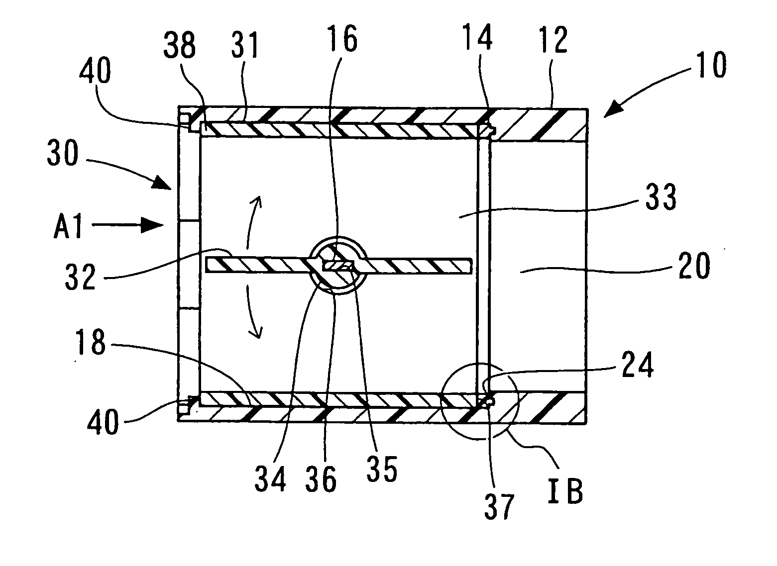
[0027] A first example embodiment of an intake device will be described with reference to FIGS. 1A to 5B. Although not illustrated, an intake device 10 shown in FIGS. 1A to 3 is for example disposed between a surge tank and an intake manifold. For example, intake air having passed through an air cleaner is drawn in the non-illustrated surge tank. The intake air flows from the surge tank into the non-illustrated intake manifold through the intake device 10. In FIG. 1, an arrow A1 denotes a flow direction of the intake air.

[0028] The non-illustrated intake manifold has plural intake air passages having different lengths. The intake device 10 distributes the intake air into the air intake passages of the non-illustrated intake manifold.

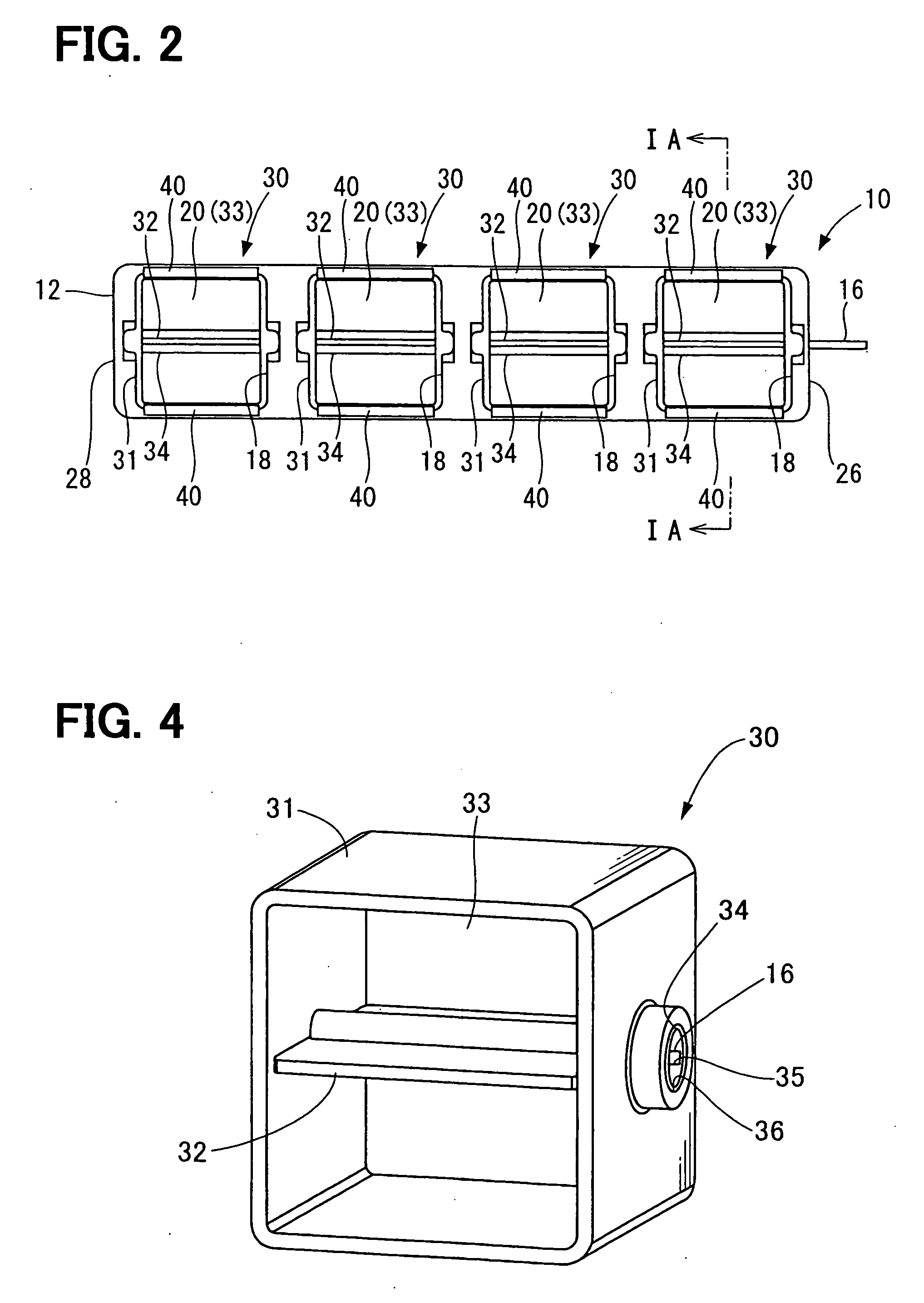
[0029] As shown in FIGS. 1A to 3, the intake device 10 has an intake manifold 12, valve units 30, sealing members 14 as deformed members, and a shaft 16. The intake manifold 12 is made of resin and forms plural housing chambers 18. Each of the housing ...

second example embodiment

[0054] A second example embodiment of the intake device 10 will be described with reference to FIGS. 6A, 6B and 7. Here, like components are denoted by like reference characters and a description thereof is not repeated. As shown in FIGS. 6A, 6B and 7, the intake device 10 has a cover plate 50, in place of the fixing portions 40 of the first example embodiment.

[0055] The cover plate 50 is disposed on an upstream end surface of the intake manifold 12, which is on a side opposite to the sealing member 14. The cover plate 50 has openings 51. Each of the openings 51 has a shape corresponding to the shape of each housing chamber 18 of the intake manifold 12. The cover plate 50 is made of resin. The cover plate 50 is fixed to the intake manifold 12 such as by thermal adhesion or welding.

[0056] Further, the cover plate 50 is fixed to the intake manifold 12 such that the upstream end 38 of each valve unit 30, which is on a side opposite to the sealing member 14, contacts the cover plate 5...


PUM

PropertyMeasurementUnit
Flow rateaaaaaaaaaa
Shapeaaaaaaaaaa

Abstract

An intake device has an intake manifold, valve units each having a valve housing and a valve member, a shaft and deformed members. The intake manifold defines passages through which a fluid flows. Each of the valve units is disposed in a corresponding one of the passages of the intake manifold such that a passage of the valve unit is in communication with the passage of the intake manifold. The shaft passes through the intake manifold and the valve units, and rotatably supports the valve members. Further, each of the deformed members is disposed between the valve housing and the intake manifold and deformed therebetween.

Description

CROSS REFERENCE TO RELATED APPLICATION [0001] This application is based on Japanese Patent Application No. 2005-228675 filed on Aug. 5, 2005, the disclosure of which is incorporated herein by reference. FIELD OF THE INVENTION [0002] The present invention relates to an intake device for an engine and a mounting structure of a valve unit. BACKGROUND OF THE INVENTION [0003] For example, an intake device constructed of valve units and an intake manifold defining intake air passages is known. Each valve unit has a resinous valve member for switching a flow of intake air and a resinous housing. The valve member and the housing are integrated into a unit, and then mounted to the intake air passage of the intake manifold. This kind of intake device is for example disclosed in Japanese Patent Publication No. 2003-509634 (U.S. Pat. No. 6,979,130 B1). [0004] In such an intake device, dimensional allowances are required between the valve member and the housing and between the housing and the in...

Claims


Application Information

Patent Timeline
IPC IPC(8): F02D9/10F02D9/08F16K1/22
CPCF02D9/1035F02D9/107F02D9/1095F16K1/222F02M35/10321F02M35/112F02M35/10085
Inventor AKAGAWA, MASAMICHI
Owner DENSO CORP
Why Eureka
Try Eureka