Dual point active flow control system for controlling air vehicle attitude during transonic flight

a technology of active flow control and transonic flight, which is applied in the direction of aircraft navigation control, boundary layer control, drag reduction, etc., can solve the problems of increasing manufacturing cost, increasing weight, and generally requiring substantial infrastructur

Inactive Publication Date: 2007-02-08
THE BOEING CO
View PDF28 Cites 14 Cited by
  • Summary
  • Abstract
  • Description
  • Claims
  • Application Information

AI Technical Summary

Benefits of technology

[0007] In yet another aspect, the present invention includes a method for controlling the attitude of an air vehicle including an airfoil having first and second surfaces, upstream and downstream orifices positioned in the first surface, and an actuator positioned in the airfoil and operatively connected to the orifices. The method includes operating the air vehicle so a transonic condition exists adjacent the airfoil. The method further includes selectively drawing air into the upstream orifice from a supersonic flow region adjacent the first surface at an angle of about 90° with the first surface and selectively directing air out of the downstream orifice and into the supersonic flow region at an angle of about 90° with the first surface. The method also includes preventing air from being drawn into or directed out of the airfoil through the second surface.

Problems solved by technology

For example, these systems generally require substantial infrastructure, including hinge structures, hydraulic or pneumatic actuators, and complex under-surface fluid delivery systems to drive the actuators.
This infrastructure increases vehicle complexity, thereby increasing manufacturing cost, and increases weight, thereby reducing vehicle performance.
Another disadvantage of traditional flight control systems is the relatively large surface discontinuities and level mismatches between the aerodynamic control surfaces and the adjacent air vehicle surface.
That is, the control surfaces necessitate gaps between them.
These gaps and surface level mismatches reduce vehicle performance by degrading the aerodynamic characteristics of the vehicle.
Other disadvantages of traditional flight control systems include the relatively high maintenance cost associated with repairing the complex infrastructure and the relatively slow response time to actuate the aerodynamic control surfaces for changing vehicle attitude.
In addition, traditional air vehicle control systems produce relatively high amounts of unwanted aeroacoustic noise during transonic flight.

Method used


Image

  • Dual point active flow control system for controlling air vehicle attitude during transonic flight
  • Dual point active flow control system for controlling air vehicle attitude during transonic flight
  • Dual point active flow control system for controlling air vehicle attitude during transonic flight

Examples


Embodiment Construction

[0016] The present invention relates to air vehicles and, more particularly, to air vehicles having an active flow control system for controlling vehicle attitude during transonic flight. Although the devices, systems, and methods for using them consistent with the present invention are primarily discussed with reference to air vehicles, they may be applied to other products (e.g., watercraft and land vehicles) without departing from the scope of the present invention.

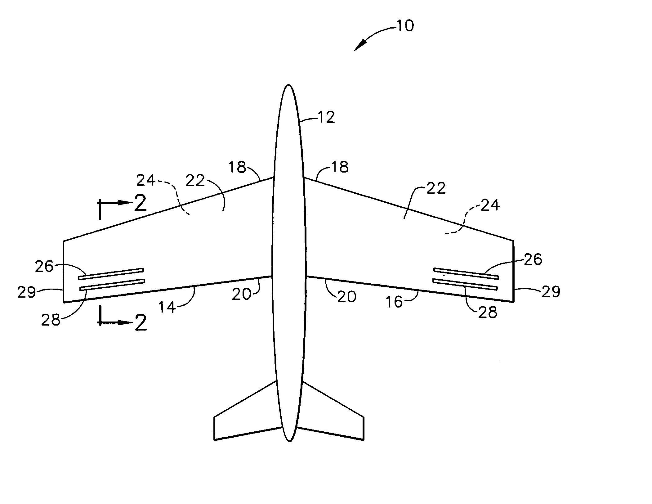
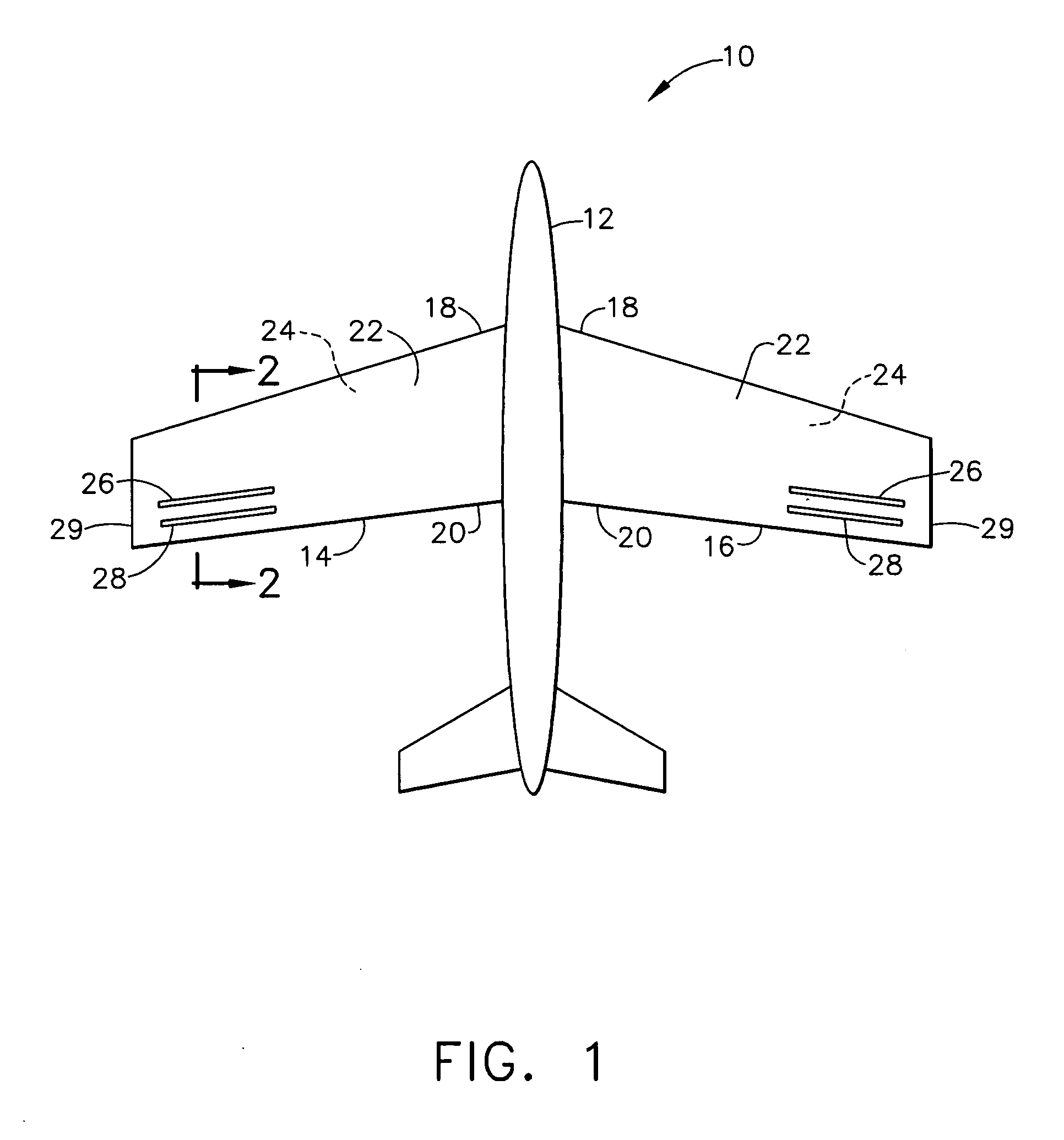
[0017] Referring now to the figures, and more particularly to FIG. 1, an air vehicle according to a first embodiment of the present invention is designated in its entirety by reference number 10. The air vehicle 10 has a fuselage 12 and opposite first and second wings 14, 16, respectively, extending laterally from the fuselage. Each wing 14, 16 has a leading edge 18, a trailing edge 20, an upper (or first) surface 22 extending between the edges, and a lower (or second) surface 24 extending between the edges below the ...


PUM


Abstract

An air vehicle having a fuselage and two wings extending laterally therefrom and having a first surface between leading and trailing edges and an opposite second surface. The vehicle includes adjacent upstream and downstream orifices positioned on at least one first surface. Each upstream orifice is closer to the leading edge than the downstream orifice. Each second surface is substantially free of orifices. The vehicle includes an actuator within each wing having orifices. Each actuator is connected to corresponding upstream and downstream orifices for creating a negative pressure differential at the upstream orifice and a positive pressure differential at the downstream orifice so air is drawn into the upstream orifice and air is pushed away form the downstream orifice. The orifice is configured so air is drawn into and directed out of the upstream and downstream orifices, respectively, at an angle of about 90% with respect to the first surface.

Description

BACKGROUND OF THE INVENTION [0001] The present invention relates to air vehicles and, more particularly, to air vehicles having an active flow control system for controlling vehicle attitude during transonic flight. [0002] Attitude of air vehicles, including aircraft and missiles, is typically controlled using systems having aerodynamic control surfaces, such as flaps, spoilers, ailerons, rudders, elevators, and fins. These traditional flight control systems have numerous disadvantages. For example, these systems generally require substantial infrastructure, including hinge structures, hydraulic or pneumatic actuators, and complex under-surface fluid delivery systems to drive the actuators. This infrastructure increases vehicle complexity, thereby increasing manufacturing cost, and increases weight, thereby reducing vehicle performance. [0003] Another disadvantage of traditional flight control systems is the relatively large surface discontinuities and level mismatches between the a...

Claims


Application Information

Patent Timeline
Patent Type & Authority Applications(United States)
IPC IPC(8): A62C27/00A62C25/00B64D1/18
CPCB64C15/14B64C2230/02Y02T50/166Y02T50/10
Inventor HASSAN, AHMED A.BILLMAN, GARRETT M.MADSEN, CASEY L.
Owner THE BOEING CO
Why Eureka
Try Eureka