Fishing reel component

Active Publication Date: 2007-02-08
SHIMANO INC
View PDF9 Cites 13 Cited by
  • Summary
  • Abstract
  • Description
  • Claims
  • Application Information

AI Technical Summary

Benefits of technology

[0017] The fishing reel component pertaining to a second aspect of the present invention is the fishing reel component according to the first aspect of the present invention, wherein the mounting space is coaxially formed with the pass-through portion to be in a round shape and the spring member is composed of a resilient wire. In addition, the fishing reel component includes a C-shaped connecting portion that connects an end of one of the pair of engagement portions and an end of the other of the pair of engagement portions and also wraps around the other end of one of the pair of engagement portions and the other end of the other of the pair of engagement portions. In this configuration, the pair of engagement portions are connected by the C-shaped connecting portion. Therefore, the shape of the spring member becomes approximately a round shape. In addition, the mounting space is coaxially formed with the pass-through portion and also formed to be in a round shape. Therefore, it becomes easy to mount the spring member engaged with the annular groove of the shaft member to the mounting space by the engagement portions.
[0018] The fishing reel component pertaining to a third aspect of the present invention is the fishing reel component according to the first aspect or the second aspect of the present invention, wherein the spring arrangement member is a bearing for rotatably supporting the component unit with respect to the shaft member. In this configuration, even if the component unit is rotatably supported by the bearing, it is possible to shorten the length of the detachable/reattachable structure in the axial direction.
[0019] The fishing reel component pertaining to a fourth aspect of the present invention is the fishing reel component according to one of the first through third aspects of the present invention, wherein the push operation portion has a tubular member and a bottom portion. The tubular member is movably mounted to the lid member in the axial direction, and at least a portion of the tubular member is arranged on the outer circumferential side of the shaft member. The bottom portion is formed integrated with an end of the tubular portion and exposed outward from the center of the lid member. In addition, the pair of tapered portions is formed by cutting a- portion of the tubular member. In this configuration, the tapered portion is formed on the tubular portion of the push button. Therefore, the length of the push button in the axial direction is shortened, compared to a configuration in which the tubular portion and the tapered portion are separately provided. Thus it is possible to further shorten the length of the detachable/reattachable structure using the pus

Problems solved by technology

Therefore, it is less convenient to perform the detachment/reattachment operation of the sp

Method used


Image

  • Fishing reel component
  • Fishing reel component
  • Fishing reel component

Examples


Example

Second Embodiment

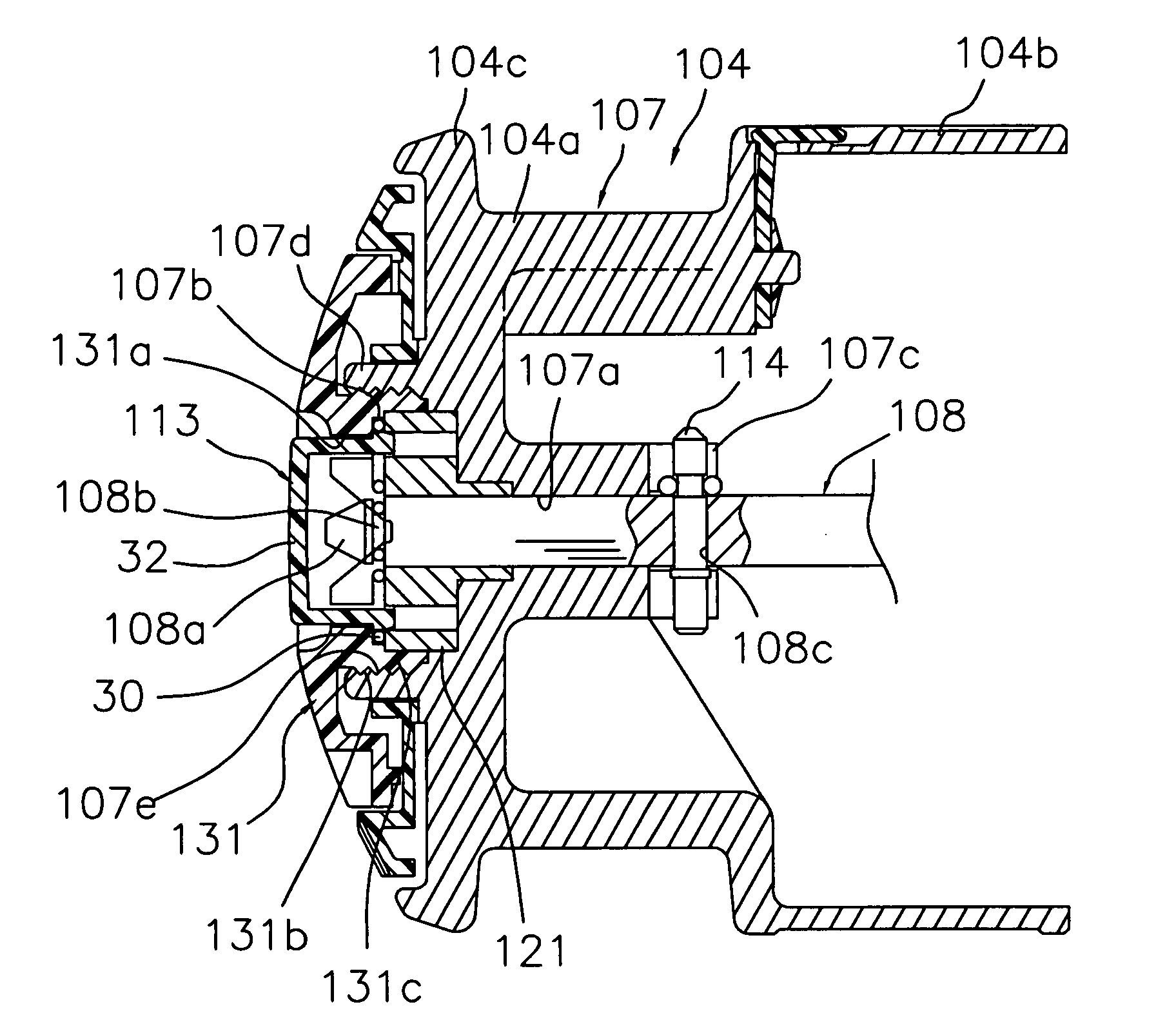
[0072] Referring now to FIG. 8, a fishing reel component in accordance with a second embodiment will now be explained. In view of the similarity between the first-and second embodiments, the parts of the second embodiment that are identical to the parts of the first embodiment will be given the same reference numerals as the parts of the first embodiment. Moreover, the descriptions of the parts of the second embodiment that are identical to the parts of the first embodiment may be omitted for the sake of brevity.

Example

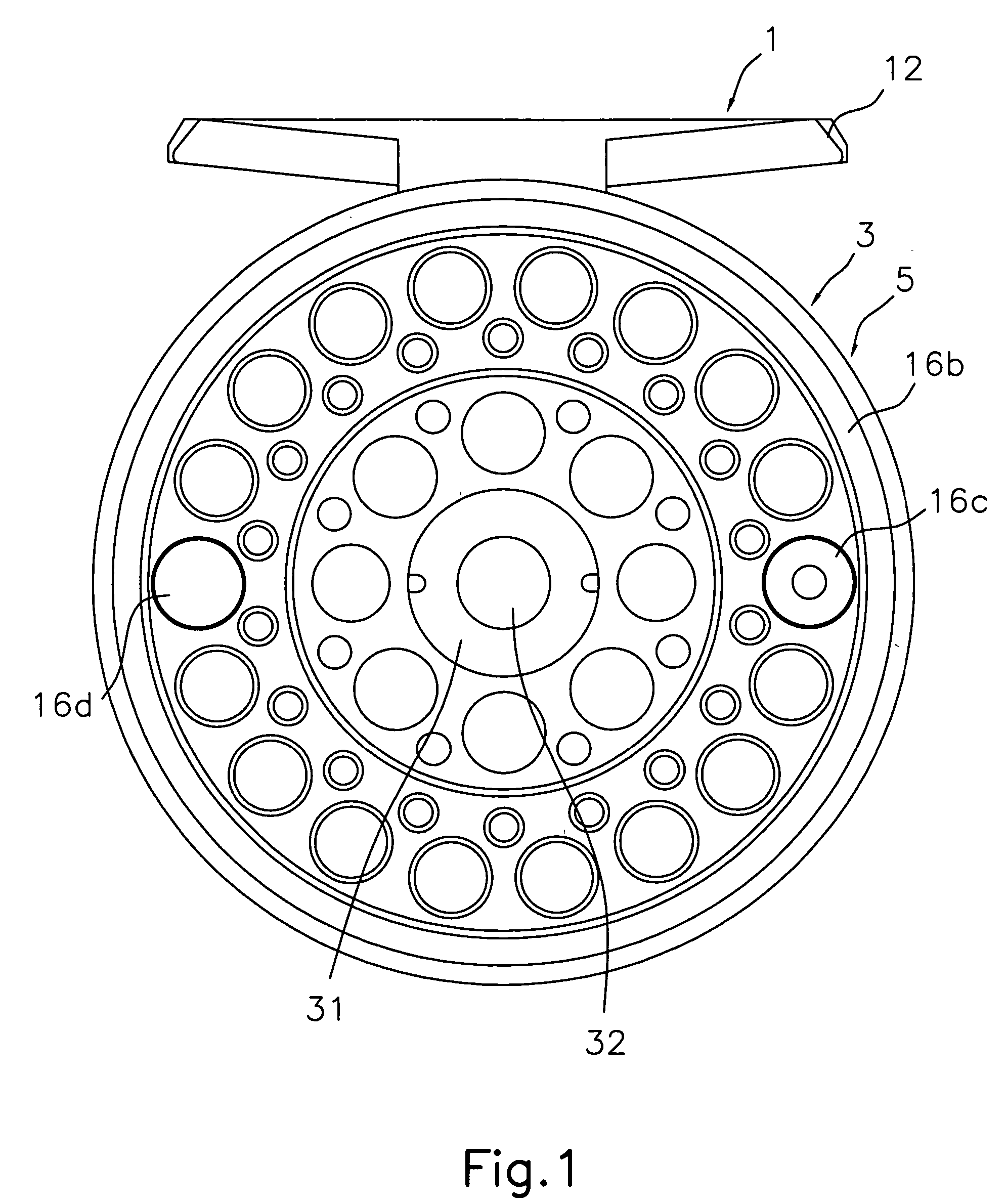
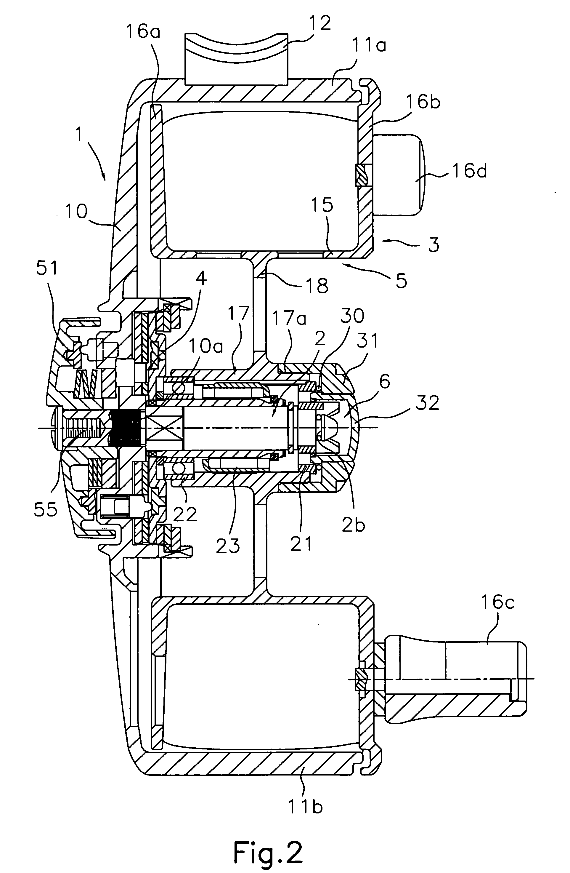
[0073] In the first embodiment, the spool 3 of the single-bearing reel was described as an example of a fishing reel component. However, the present invention is not limited thereto. It will be apparent to one of skill in the art from this disclosure that the present invention can be applied to any fishing reel component as long as it is detachably / reattachably mounted to a shaft member. For example, in the second embodiment, a fishing reel component is applied to a spool 104 of a spinning reel. The fishing reel component is detachably / reattachably mounted to a spool shaft 108.

[0074] Referring to FIG. 8, the spool 104 is arranged between a first arm and a second arm of a rotor (not shown). The spool 104 is detachably / reattachably mounted with a one-touch operation and non-rotatably mounted on a tip of the spool shaft 108. The spool shaft 108 includes a tapered head 108a, an annular groove 108b and a pin hole 108c. The tapered head 108a is formed at the tip of the spool shaft 108. T...


PUM


Abstract

A fishing reel component includes a boss, a spring member, a lid member, a push button and spring arrangement member. The boss forms a boss through hole and a mounting space. The spring member is mounted in the mounting space. The spring member includes first and second engagement portions arranged to oppose each other. The lid member is fixed to the boss to retain the spring member and cover the mounting space. The push button includes a plurality of tapered portions. The tapered portions protrude from the push operation portion in the axial direction. The spring arrangement member arranges the spring member between the lid member and the spring arrangement member. The spring arrangement member includes a plurality of first through holes with each of the first through holes being configured for one of the tapered portions to pass therethrough.

Description

CROSS-REFERENCE TO RELATED APPLICATIONS [0001] This application claims priority under 35 U.S.C. § 119 to Japanese Patent Application No. 2005-210536. The entire disclosure of Japanese Patent Application No. 2005-210536 is hereby incorporated herein by reference. BACKGROUND OF THE INVENTION [0002] 1. Field of the Invention [0003] The present invention generally relates to a fishing reel component. More specifically, the present invention relates to a fishing reel component that can be detached from a shaft member or reattached to a shaft member of a fishing reel with a one-touch operation. [0004] 2. Background Information [0005] A spool or fishing reel component for a spinning reel has been known which is detached from a spool shaft or reattached to a spool shaft or a shaft member with a one-touch operation performed by pushing a push button. (See, for example, Japan Utility Model Application Publication JP-U-06-068447.) A conventional one-touch detachable / reattachable spool is detac...

Claims


Application Information

Patent Timeline
IPC IPC(8): A01K89/00
CPCA01K89/01A01K89/016A01K89/0111A01K89/033A01K89/015
Inventor MORISE, TAISEI
Owner SHIMANO INC
Why Eureka
Try Eureka