
Optical pickup

Inactive Publication Date: 2005-11-10
SONY CORP
View PDF2 Cites 2 Cited by
  • Summary
  • Abstract
  • Description
  • Claims
  • Application Information

AI Technical Summary

Benefits of technology

[0013] More particularly, regarding the reduction in size of the optical pickup device, the shorter the route in which the light emitted from the laser diode is returned to the laser diode itself is, the stronger the interference arises due to the light in the laser diode. Accordingly, the length of the optical path is shortened, and hence a laser noise component is generated due to the interference between the emitted light and the return light in higher probability.

Problems solved by technology

More particularly, regarding the reduction in size of the optical pickup device, the shorter the route in which the light emitted from the laser diode is returned to the laser diode itself is, the stronger the interference arises due to the light in the laser diode.
Accordingly, the length of the optical path is shortened, and hence a laser noise component is generated due to the interference between the emitted light and the return light in higher probability.
Regarding the low power consumption, a drive IC for superposing and a high frequency on a laser diode to drive the laser diode has a large power consumption, and hence this is contrary to the demand for the low power consumption.
The self-excited oscillation laser has principally a higher operation current as compared with a so-called single-mode laser, and this also opposes to the demand for the low power consumption.

Method used


Image

  • Optical pickup
  • Optical pickup
  • Optical pickup

Examples


Embodiment Construction

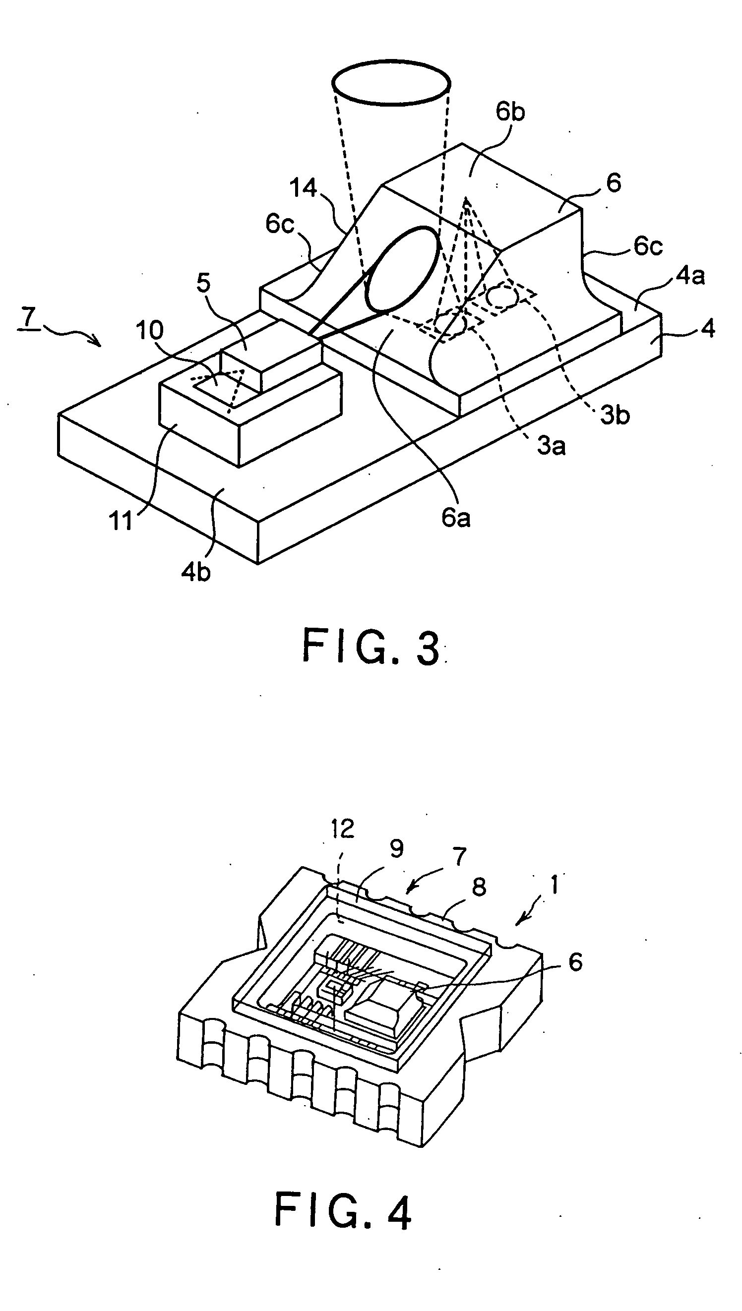
[0025] Hereinafter, an optical pickup to which the present invention is applied will be described in more detail with reference to the accompanying drawing. An optical system of the optical pickup according to the present invention uses an optical integrated element so-called a laser coupler of the structure that a light emitting element and a light-receiving element are disposed in a hybrid manner. This laser coupler 1 contains, as shown in FIG. 3 and FIG. 4, a laser coupler chip 7 having a laser diode 5 of light emission source and a microprism 6 mounted on one silicon chip 4 having photodetectors 3a and 3b for photodetecting provided on a surface region, for example, in a flat package 8.

[0026] The silicon chip 4 of the laser coupler chip 7 is formed in a substantially rectangular shape, and has photodetectors 3a and 3b formed by diffusion, etc. on a silicon wafer and formed by dicing the silicon wafer in a substantially rectangular shape. A microprism 6 is provided at one end 4a...


PUM


Abstract

The present invention relates to a removal of a noise due to an interference between an emitted light from a light emitting element of laser beam for reading a signal from an optical disc and a return light from the optical disc. The present invention provides a pickup device for reading a signal from an optical disc, including a light emitting element that emits a laser beam irradiated on the optical disc, an objective lens that condenses the laser beam emitted from the light emitting element on a signal recording surface of the optical disc, a light-receiving element that receives a return light reflected on the signal surface of the optical disc, and a noise removing section removing the noise component generated by the interference between the emitted light and the return light, the noise removing section being arranged in an optical path having a route for the emitted light and the return light.

Description

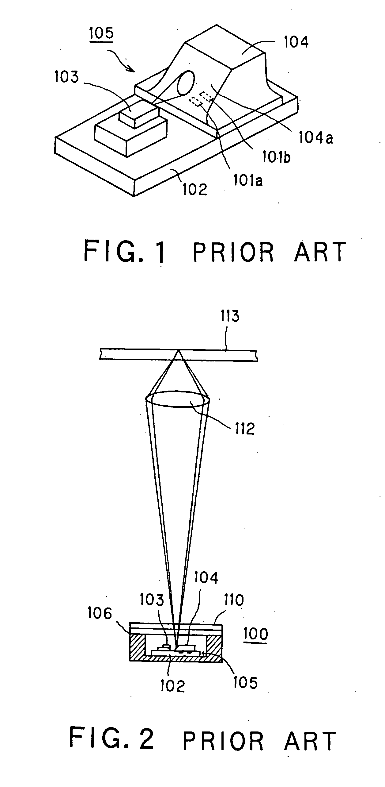
CROSS REFERENCES TO RELATED APPLICATIONS [0001] The present invention contains subject matter related to Japanese Patent Application JP 2004-140464, filed in the Japanese Patent Office on May 10, 2004, the entire contents of which being incorporated herein by reference. BACKGROUND OF THE INVENTION [0002] 1. Field of the Invention [0003] The present invention relates to an optical pickup for recording and reproducing an information signal in an optical disc, and more particularly to an optical system of the optical pickup. [0004] 2. Description of Related Art [0005] In an optical pickup device for recording or reproducing an optical recording medium, as shown in FIG. 1, many optical integrated elements so-called a laser coupler of the structure that a light emitting element and a light-receiving element are disposed in a hybrid manner, has been heretofore produced. [0006] A laser coupler 100 includes, as shown in FIG. 1 and FIG. 2, a laser coupler chip 105 which mounts a laser diode ...

Claims


Application Information

Patent Timeline
IPC IPC(8): G11B7/135G11B7/00G11B7/12G11B7/123G11B7/13G11B7/1381
CPCG11B7/1381G11B7/1205G11B7/123G11B7/1365G11B7/1369
Inventor ABE, TSUGUHIRO
Owner SONY CORP
Learn More