[0024]Embodiments of the present invention will be described in detail below with reference to FIGS. 1 to 7.
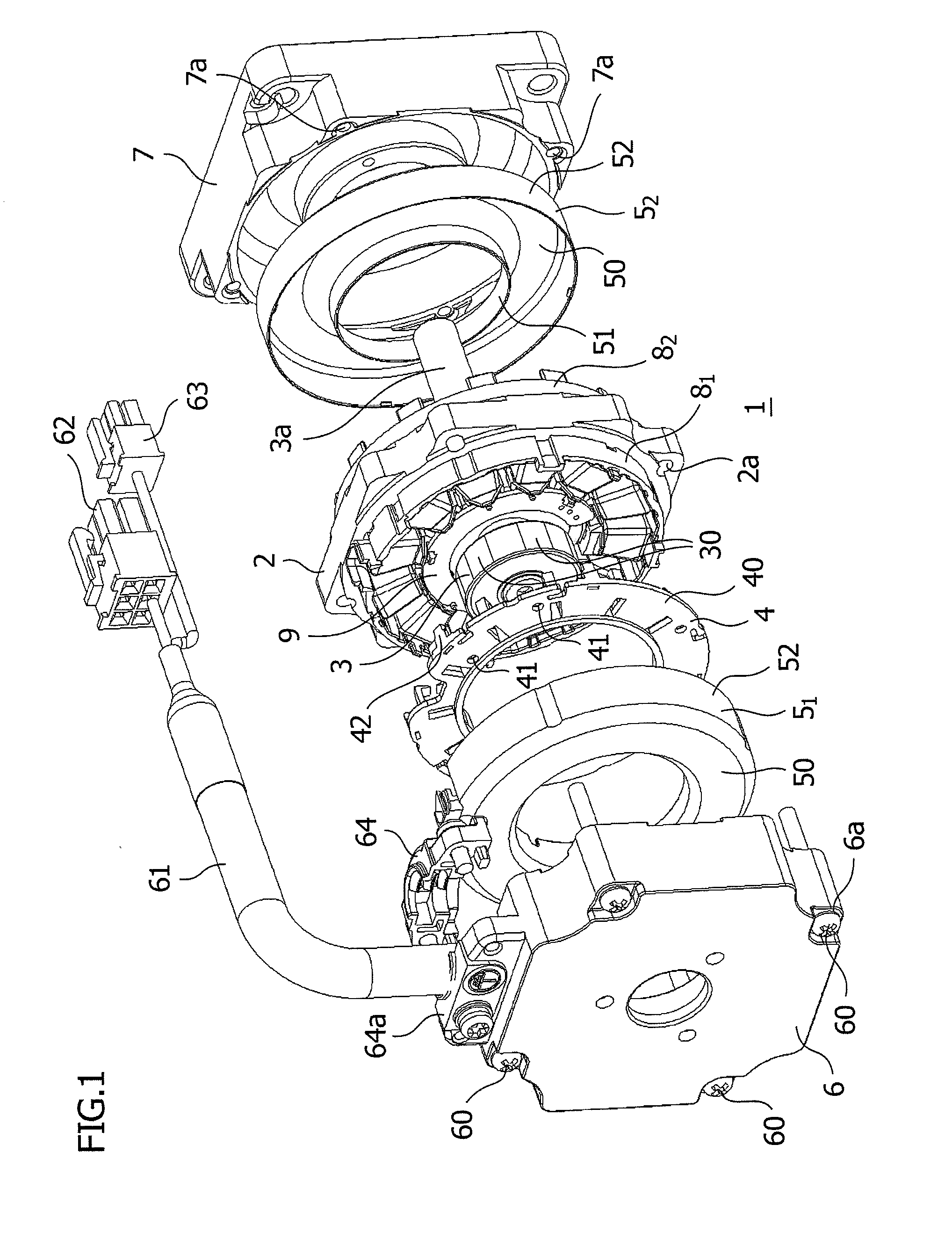
[0025]Referring to FIG. 1, which is an exploded view of a brushless motor, a brushless motor 1 is constituted by a stator 2, a rotor 3 arranged on an axis of the stator 2, a lead clamping plate 4 assembled on one side of the stator 2, a pair of coil end covers 51, 52 assembled on both sides of the stator 2, and a bracket 6 and a flange 7 that are assembled on the further outside of the coil end covers 51, 52, and these components are integrally assembled. A motor case of the brushless motor 1 is constituted by the bracket 6, the flange 7, and an outer surface of the stator 2.
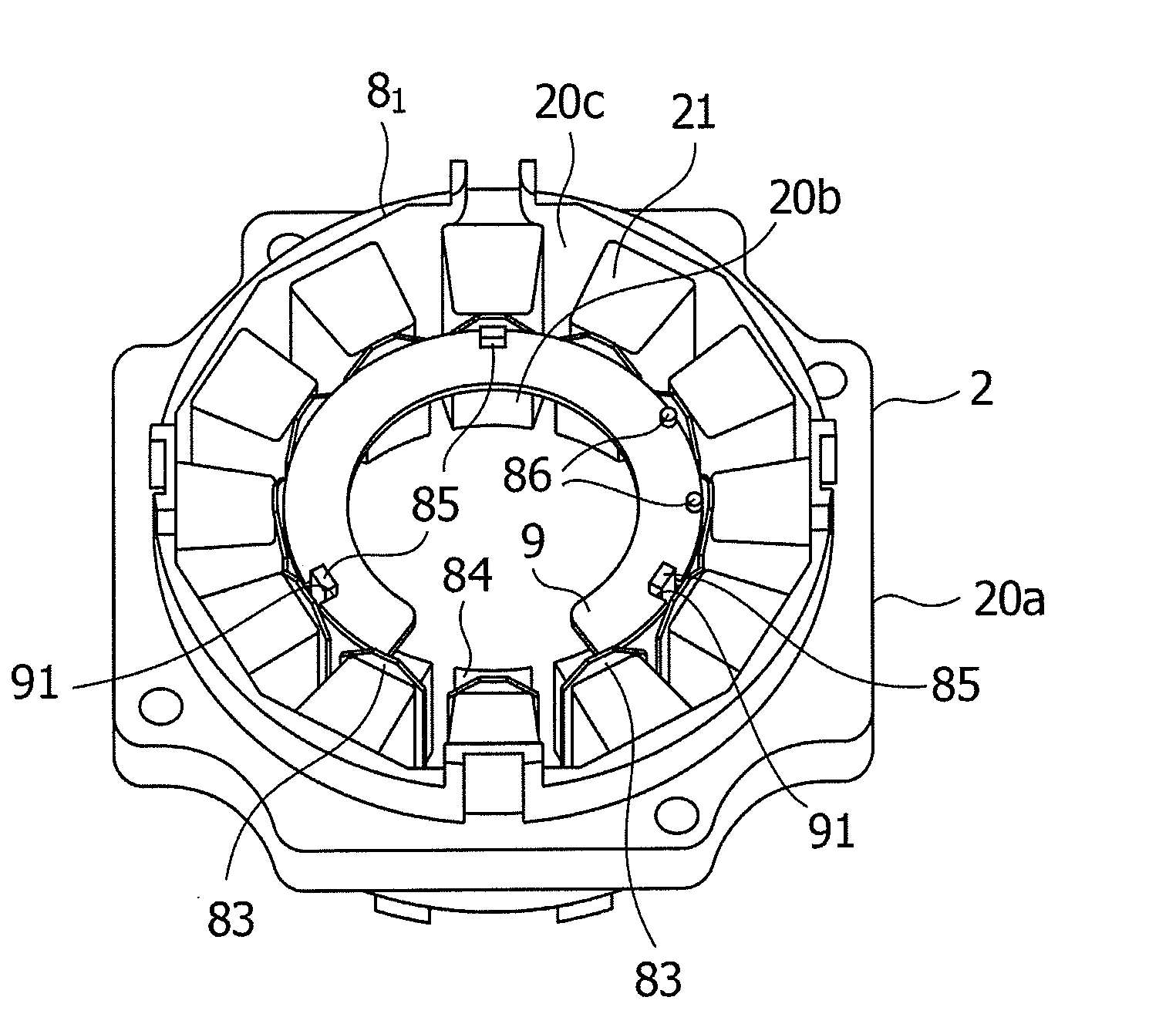
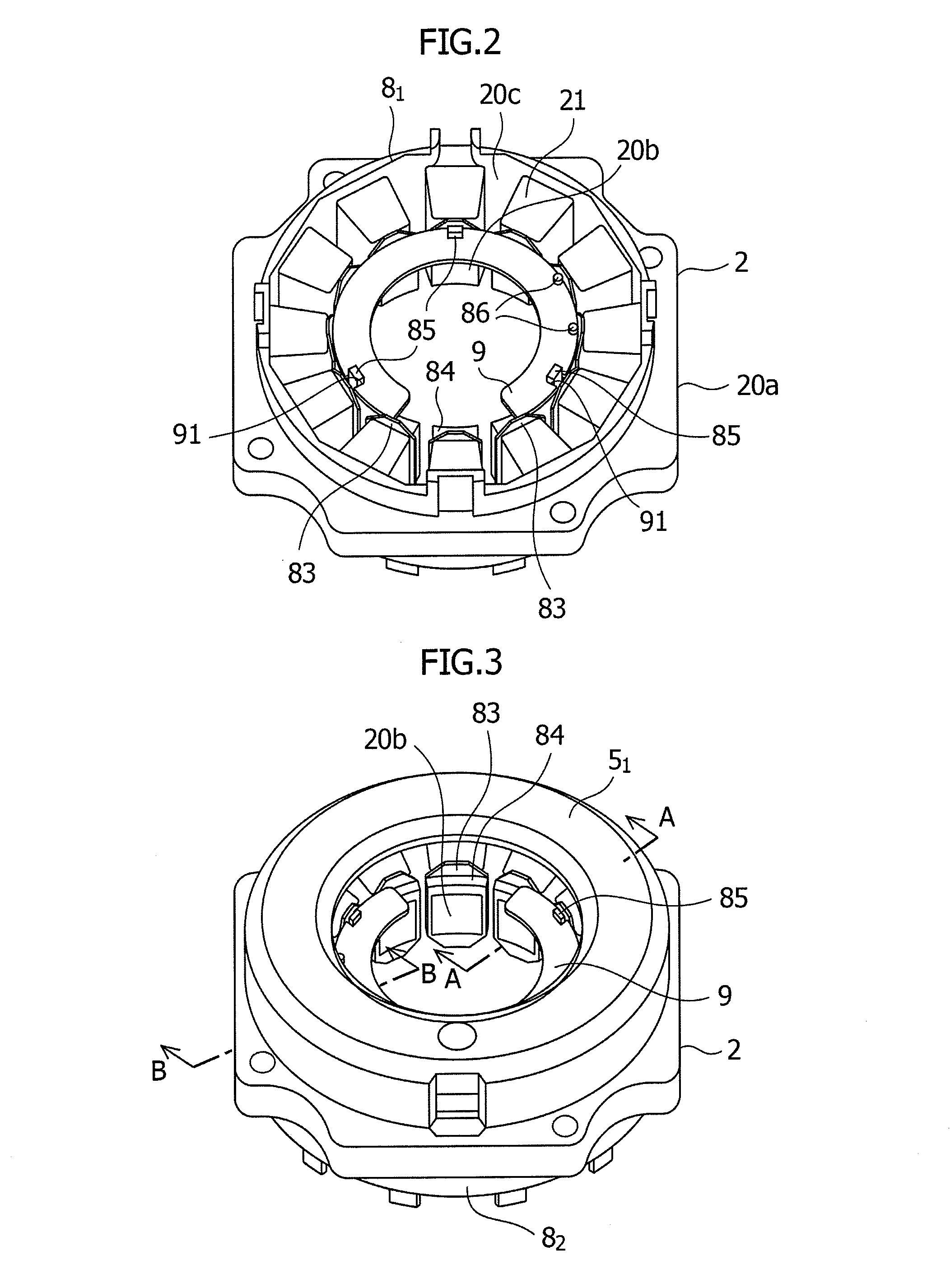
[0026]Referring to FIG. 2, the stator 2 of the brushless motor 1 includes pole teeth 20b formed at an inside of a yoke 20a formed on the periphery of the pole teeth 20 and including thin punched steel plates having been produced by pressing steel plates such as silicon steel plates and laminated together, a stator core 20 including a slot 20c formed between the pole teeth 20, a pair of stator covers (also referred to as “insulators”) 81, 82 that are assembled from both sides of the stator core 20 and insulate the inner surface side of the yoke 20a from the periphery of the pole teeth 20 except the inner surface thereof, and a stator coil 21 wound around the pole teeth 20 of the stator covers 81, 82.
[0027]The rotor 3 is concentrically arranged on the axis of the stator 2, and permanent magnets 30 are provided on a peripheral surface of the rotor 3 with a predetermined space.
[0028]FIG. 6 illustrates the stator cover 81. The stator cover 81 is an insulating member prepared by using a resin material molded by injection molding, for example. Pole tooth cover portions 82 having an inverted U-shaped cross section are radially extended on the inner surface of the ring-shaped ring portion 81 in the circumferential direction with a predetermined space. The pair of stator covers 81, 82 is assembled from above and below so as to sandwich and cover the stator 2 on both sides thereof and particularly insulates the periphery of the pole teeth 20b and the inside of the yoke 20a from the outside. The stator coil 21 is wound by a coil winding machine around the outside of the pole tooth cover portion 82, which covers the periphery of the pole teeth 20b. A trapezoidal stopper wall 83 is protruded from the inner diameter side of the pole tooth cover portion 82 of at least one stator cover 81 toward the outside in the axial direction to prevent the coming off of the stator coil 21. Pedestal parts 84 that are extensions from the pole tooth cover portion 82 toward the central axis are formed on the inner surface side of the stopper wall 83 provided on the pole tooth cover portion 82. The pedestal parts 84 provided on the upper portion of the stopper walls 83 of the pole tooth cover portions 82 form a substantially ring-shaped pedestal part as a whole, and an arc-shaped sensor substrate 9 is mounted on the pedestal parts 84.
[0029]Referring to FIGS. 2 and 4, the sensor substrate 9 includes a substantially ring-shaped printed board 90 to which a rotational position detection element such as a Hall IC is assembled separately from other electronic parts for controlling the motor. On the printed board 90, a predetermined number of cutouts 91 are formed in outer periphery portions and plural positioning recessed portions 92 are formed at predetermined locations on the periphery of the board surface.
[0030]Referring to FIGS. 6 and 7, claw portions 85 and pins (one or more pins, for example) 86 are protruded in the axial direction from some of the pedestal parts 84, i.e., from three or more pedestal parts 84, as locking portions. The sensor substrate 9 is positioned and fixed in the circumferential direction by preventing the coming off of the stator coil 21 by allowing the claw portions 85 to engage with the cutouts 91 and allowing the pins 86 to engage with the positioning recessed portion 92. On each of the pedestal parts 84 on which the claw portion 85 is provided, a step portion 84a that is formed lower by one step is provided, and the claw portion 85 is erected on the step portion 84a to secure the sufficient length of an axial portion 85a of the claw portion 85. A predetermined gap portion 87 is provided between the claw portion 85 and the stopper wall 83, and an inner cylindrical portion 51 of at least one of the coil end cover 51 is assembled to the gap portion 87. Referring to FIGS. 3 to 5, in the coil end covers 51, 52, the inner cylindrical portion 51 is provided on an inner periphery side of a ring-shaped lid portion 50 and an outer cylindrical portion 52 is provided on an outer periphery side of the ring-shaped lid portion 50. In the outer cylindrical portion 52, a claw portion 52a provided on the inside of the leading edge of the outer cylindrical portion 52 is assembled to a protrusion 81a provided on an outer surface of a ring 81 of the stator covers 81, 82 to assemble the coil end covers 51, 52 to the stator covers 81, 82.
[0031]On the lead clamping plate 4, multiple lead outlet holes 41 are formed on a ring-shaped plate 40. Leads are drawn out through the lead outlet holes 41 for connection. The lead clamping plate 4 is assembled to at least one of the stator covers (i.e., the stator cover 81) via claw portions 42 provided on the periphery of the plate 40.
[0032]Bolt holes 6a, 7a are formed at the four corners of the bracket 6 and the flange 7 provided on the outer ends of the brushless motor 1, and the bracket 6 and the flange 7 are integrally fastened together with bolts 60 threaded through the bolt holes 6a, 7a. In addition, the bolts 60 are threaded through bolt holes 2a provided at four corners of the stator 2 to co-fasten the stator 2 between the bracket 6 and the flange 7.
[0033]The bracket 6 and the flange 7 respectively include built-in bearings (not illustrated) provided in through holes for inserting an output axis 3a of the rotor 3 to rotatably support the output axis 3a of the rotor 3.
[0034]External cables 61 including a bundle of power cables and signal cables are drawn out from the bracket 6 for connection with units such as a control unit. Connectors 62, 63 are connectors for connection with the control unit and the like.
[0035]A cable clamp 64 is assembled to a half clamping portion 64a formed integrally with the bracket 6 and retains the external cable 61.
[0036]A method for mounting the above-described sensor substrate will be described. The sensor substrate 9 is assembled to the pedestal parts 84 provided on one of the stator covers 81, 82 assembled to the stator core 20. In assembling the sensor substrate 9, the pins 86 are aligned with the positioning recessed portions 92 of the sensor substrate 9, then the claw portions 85 as the locking portions are allowed to engage with the cutouts 91, and then the sensor substrate 9 is pressed in. The pins 86 are inserted into the positioning recessed portions 92 in the above-described manner to position the sensor substrate 9, and the claw portions 85 are allowed to engage with the cutouts 91 due to the resilient force of the claw portions, and thus the sensor substrate 9 is fixed. Next, the coil end covers 51, 52 are assembled onto the stator covers 81, 82, the claw portion 52a of the outer cylindrical portion 52 on the leading edge thereof is allowed to engage with the protrusion 81a on the outer surface of the ring-shaped portion 81 of the stator covers 81, 82 to assemble the coil end covers 51, 52 to the stator covers 81, 82. In this structure, one of the coil end covers 51, 52, i.e., the inner cylindrical portion 51, is arranged in the gap portion 87 between the claw portion 85 and the stopper wall 83 as a holding member to hold the claw portion 85 on the back surface thereof, and thereby the coming off of the claw portion 85 from the cutout 91 of the sensor substrate 9, which may result from deviation in the radial direction, is regulated. Referring to FIG. 7, a width L1 of the claw portion 85 and a thickness L2 of the inner cylindrical portion 51 are set so that the sum of the width L1 and the thickness L2 becomes greater than a width L3 of the gap portion 87, and thereby the coming off of the claw portion 85 is prevented. As described above, the sensor substrate 9 can be held by the claw portions 85 at a set position, and thereby the coming off of the sensor substrate 9 from the pedestal parts 84 can be prevented.
[0037]Note that the present invention is not limited to the above-described embodiment, and an insulating structure equivalent to the stator covers 81, 82 can also be formed by using a stator core 20 integrally molded by resin molding instead of using the pair of stator covers 81, 82 which insulates the periphery of the pole teeth 20 formed in the inside of the yoke 20a assembled to the stator core 20 from both sides thereof.
[0038]In addition, the numbers of the positioning recessed portions 92 and the cutouts 91 provided on the sensor substrate 9 can be freely set as necessary, and the numbers of the claw portions 85 and the pins 86 provided on the stator covers 81, 82 can be freely set so that they comply with the structure of the sensor substrate 9. In addition, holes simply bored at the surface of the substrate can be used for the positioning recessed portions 92. Furthermore, the inner cylindrical portion 51 of the coil end covers 51, 52 is not always necessary and a member different from the inner cylindrical portion 51 capable of preventing the coming off of the claw portions 85 can be used. As described above, the present invention can of course be implemented by an appropriate alteration or modification thereof within the scope of the present invention so as not to change the gist of the invention.
REFERENCE SIGNS LIST
[0039] 1 Brushless motor [0040] 2 Stator [0041] 3 Rotor [0042] 4 Lead clamping plate [0043] 51, 52 Coil end cover [0044] 6 Bracket [0045] 7 Flange [0046] 81, 82 Stator cover [0047] 9 Sensor substrate [0048] 20 Stator core [0049] 20b Pole tooth [0050] 20c Slot [0051] 21 Stator coil [0052] 30 Permanent magnet [0053] 51 Inner cylindrical portion [0054] 82 Pole tooth cover [0055] 83 Stopper wall [0056] 84 Pedestal part [0057] 85 Claw portion [0058] 86 Pin [0059] 91 Cutout [0060] 92 Positioning recessed portion