Light source device capable of repressing the light surge

Inactive Publication Date: 2008-08-05
MICROTEK INT
View PDF14 Cites 3 Cited by
  • Summary
  • Abstract
  • Description
  • Claims
  • Application Information

AI Technical Summary

Benefits of technology

[0012]In view of the above-mentioned problems, it is therefore an object of the invention to provide a light source device utilizing obscuring units to partially obs

Problems solved by technology

The light surge not only tends to cause the over-saturation of the optical signals at two ends of the image sensor, but also makes the color correction computations of the software or firmware unstable and incorrectly, thereb

Method used


Image

  • Light source device capable of repressing the light surge
  • Light source device capable of repressing the light surge
  • Light source device capable of repressing the light surge

Examples


Example

[0028]The light source device capable of repressing the light surge according to the invention will be described with reference to the accompanying drawings.

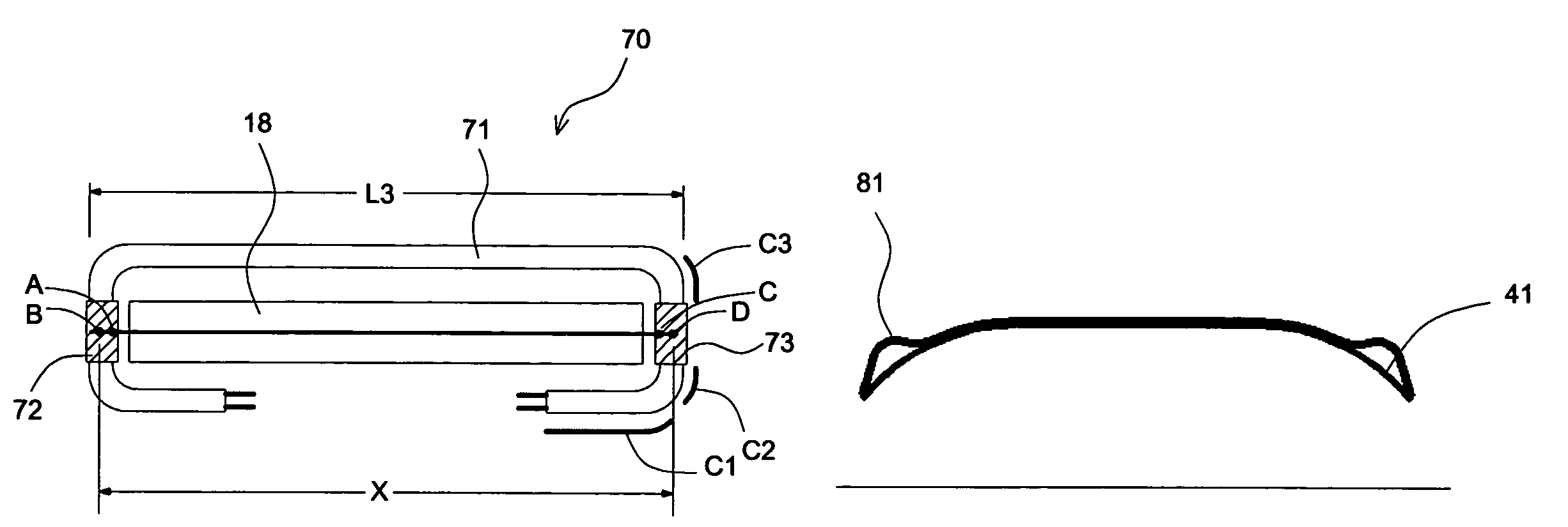
[0029]The bent lamp is used to compensate the insufficient brightness at two ends of the typical linear lamp, but the distance of the bent lamp between two ends has to be greater than the effective scan width so as to avoid the light surge. This condition limits the further reduction of the length of the lamp. The invention overcomes the limitation that the distance of the bent lamp must be greater than the effective scan width, so as to further shorten the length of the bent lamp. In addition, in order to repress the light surge, two obscuring units are utilized to obscure the light beam at two ends of the lamp close to the image signal inlet 18 so that the light at two ends of the lamp is free from being reflected to the image sensor. Hence, the flatbed scanner using the light source device of the invention may have a narrower...


PUM


Abstract

A light source device capable of repressing light surges is fixed in a flatbed scanner to provide a light beam for scanning a document. The light source device includes a bent lamp with bent parts for generating the light beam and compensating for the brightness at two ends of the bent lamp; and a set of obscuring units fixed at the two bent parts to partially obscure the light of the lamp. Hence, the light source device can repress the light surge caused on two ends of the image sensor even if the bent parts at two ends of the lamp are very close to the sides of the scanning window. Therefore, the length of the light source device can be shortened and the width of the flatbed scanner using the light source device can also be narrowed.

Description

BACKGROUND OF THE INVENTION[0001]1. Field of the Invention[0002]The invention relates to a light source device, and more particularly to a light source device capable of repressing the light surge by utilizing obscuring units to obscure portions of the light source of the bent lamp.[0003]2. Description of the Related Art[0004]FIG. 1 shows a partial architecture diagram of a conventional flatbed scanner. Referring to FIG. 1, the flatbed scanner includes a carriage 14 and a scan platen 12. A to-be-scanned document 11 is placed on the scan platen 12. The carriage 14 includes a light source device (lamp) 13, mirrors 15, a lens 16, and an image sensor 17. The image sensor 17 may be a charge coupled device (CCD). The light source device 13 includes a lamp 131 and a lamp holder 132. The carriage 14 has an image signal inlet 18 at a position close to the light source device 13, such that the scattered light reflected from the to-be-scanned document 11 may enter the carriage 14 via the image...

Claims


Application Information

Patent Timeline
IPC IPC(8): H04N1/04F21V33/00H01J61/04H01J61/32H04N1/10H04N1/193
CPCH01J61/04H01J61/325H04N1/10H04N1/02845H04N1/193
Inventor WANG, CHIH-KUANG
Owner MICROTEK INT
Why Eureka
Try Eureka