Valve gear for internal combustion engines

Inactive Publication Date: 2010-09-30
HONDA MOTOR CO LTD
View PDF1 Cites 4 Cited by
  • Summary
  • Abstract
  • Description
  • Claims
  • Application Information

AI Technical Summary

Benefits of technology

[0031]Effects of the invention include the following:
[0032]Since the spring socket for the return spring 58 of the sub-rocker arm is formed in the step that is disposed eccentrically in the axial direction of the camshaft and the return spring is supported between this socket and the holder member, the return spring 58 can be arranged compactly in the valve gear for internal combustion engines pertaining to the present invention. For example, the length that the return spring 58 occupies in the longitudinal direction of the vehicle can be shortened by arranging the socket and the holder member in the vertical direction of the vehicle and supporting the return spring in the vertical direction of the vehicle between the socket and the holder member. This enables the return spring 58 to be arranged compactly in the longitudinal direction and the longitudinal length of the cylinder heads to be shortened.
[0033]Also, as the return spring 58 is held within the vertically penetrating through hole, the longitudinal length of the cylinder heads can be shortened by arranging the return spring in the vertical direction of the vehicle and arranging the return spring 58 compactly in the longitudinal direction.
[0034]Also, as the return spring 58 is housed inside the through hole vertically penetrating the holder member, the

Problems solved by technology

The known valve gear for internal combustion engines as disclosed in JP-A 2008-208800 involves a problem that the longitudinal length of the cylinder head is increased by the arrangement of a coil spring (a sub-rocker aim return spring), which presses the sub-rocker arm constituting the link mechanism against the drive cam, in the longitudinal direction of the vehicle.
Further, as a compression coil spring (return spring)

Method used


Image

  • Valve gear for internal combustion engines
  • Valve gear for internal combustion engines
  • Valve gear for internal combustion engines

Examples


Example

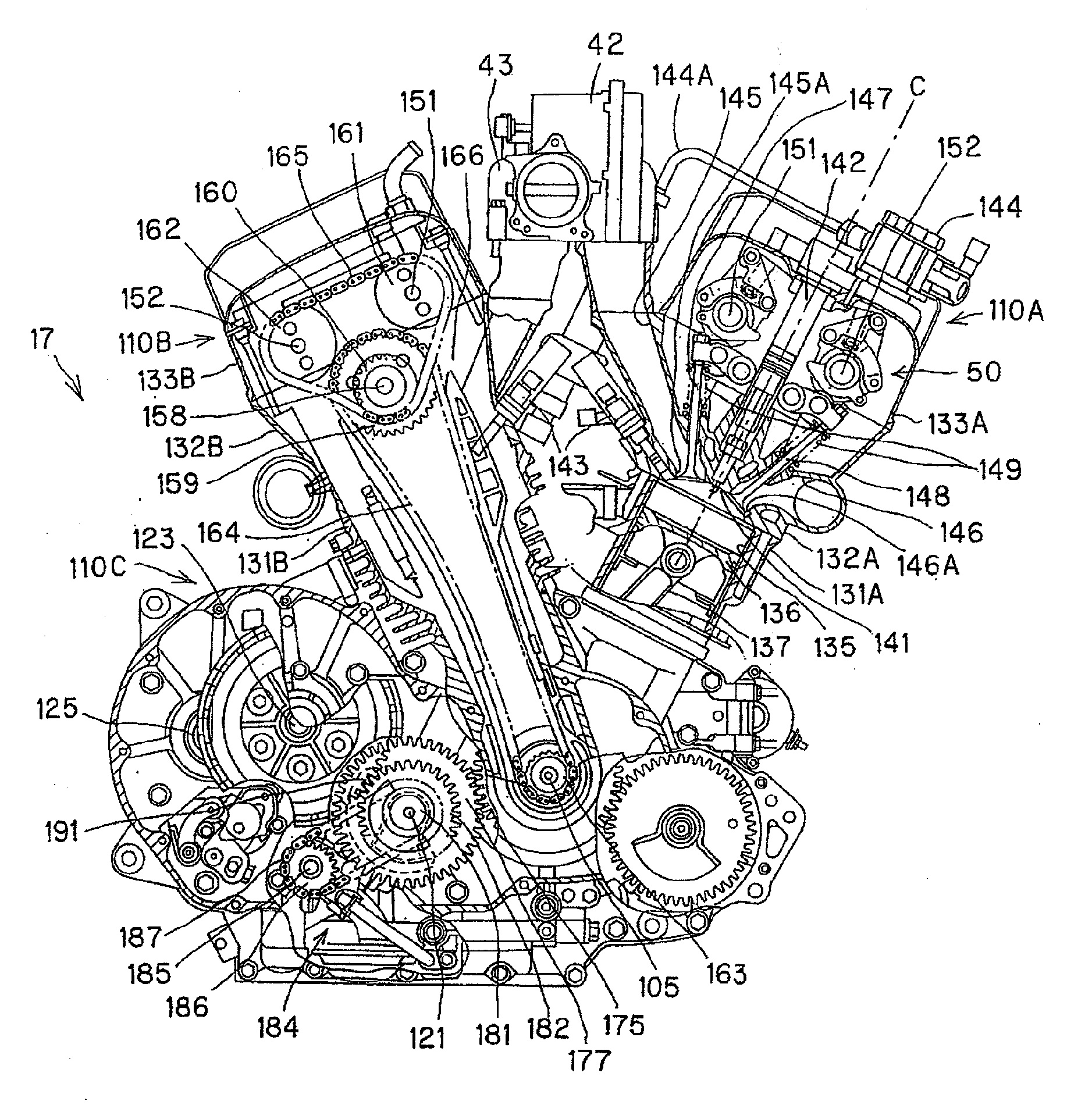
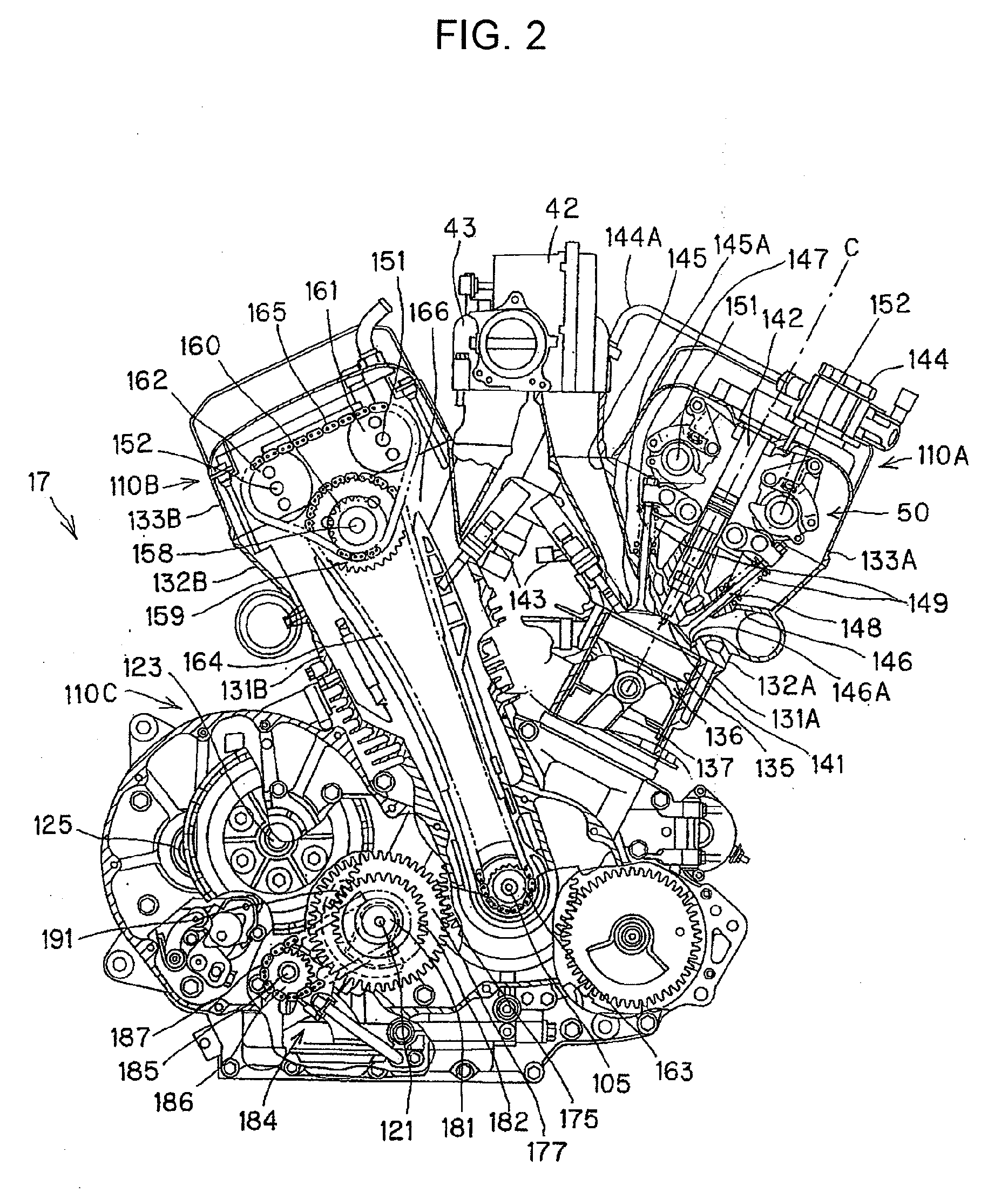
[0058]A best mode for carrying out the invention will be described below with reference to drawings. In the description, references to directions such as front or rear, left or right and up or down are with respect to the vehicle body.

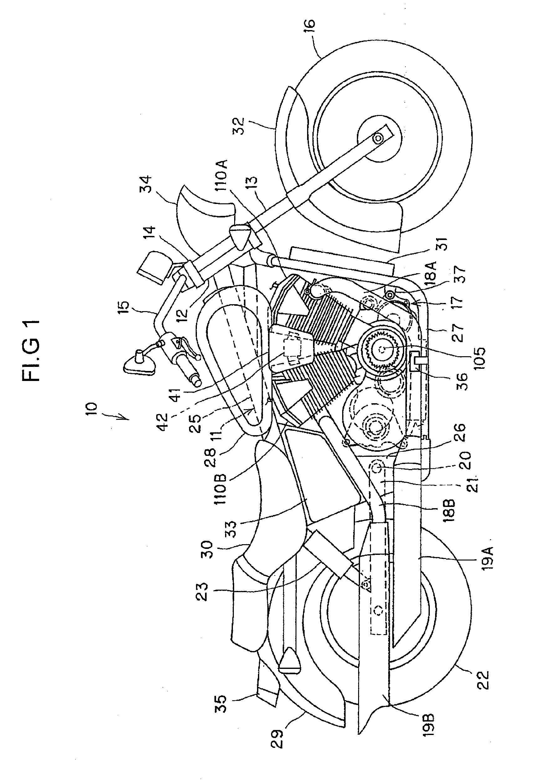
[0059]FIG. 1 is a profile of a motorcycle to which a valve gear pertaining to an exemplary embodiment of the invention is applied. This motorcycle 10 is provided with a body frame 11, a pair of left and right front forks 13 turnably supported by a head pipe 12 fitted to the front end of the body frame 11, a steering handlebar 15 fitted to a top bridge 14 supporting the upper ends of the front forks 13, a front wheel 16 turnably supported by the front forks 13, an engine 17 as an internal combustion engine supported by the body frame 11, mufflers 19A and 19B linked to the engine 17 via exhaust pipes 18A and 18B, a rear swing arm 21 supported to be vertically oscillable by a pivot 20 in the rear lower part of the body frame 11, and a rear wheel 22 turnab...


PUM


Abstract

A valve gear for an internal combustion engine having a sub-rocker arm return spring that is shortened in a longitudinal length of a cylinder. The valve gear for the internal combustion engine is provided with a camshaft, an intake cam turning integrally with the camshaft, a valve cam for opening and closing an engine valve, a link mechanism for transmitting a valve driving force to the valve cam, a holder for supporting a sub-rocker arm support and a driving mechanism for varying a fulcrum position of the link mechanism. A valve operating characteristic can be varied with an oscillating position of the sub-rocker arm support. A sub-rocker arm is provided with a roller, an eccentrically disposed step and a link section. The step is provided with a spring socket, and a return spring is arranged intervening between the spring socket and the holder.

Description

CROSS-REFERENCE TO RELATED APPLICATIONS[0001]The present application claims priority under 35 USC 119 to Japanese Patent Application No. 2009-080310 filed on Mar. 27, 2009; Japanese Patent Application No. 2009-080311 filed on Mar. 27, 2009; Japanese Patent Application No. 2009-080312 filed on Mar. 27, 2009, the entire contents of which are hereby incorporated by reference.BACKGROUND OF THE INVENTION[0002]1. Field of the Invention[0003]The present invention relates to a valve gear for an internal combustion engine, the device being provided with a function to make variable the valve operating characteristics of the opening and dosing of engine valves.[0004]2. Description of Background Art[0005]Valve gears are known for internal combustion engines is provided with a drive cam that rotates integrally with a camshaft supported by cylinder heads, a valve cam that is oscillably supported by the camshaft and opens and closes engine valves, a link mechanism that is oscillably supported cent...

Claims


Application Information

Patent Timeline
IPC IPC(8): F01L1/34F01L1/02
CPCF01L1/267F01L13/0063Y10T74/20882F01L2013/0073Y10T74/2107F01L2001/0537
Inventor CHO, MASAKISATO, TOSHIYUKIIMAFUKU, TAKAHIRO
Owner HONDA MOTOR CO LTD
Why Eureka
Try Eureka