
Gearbox for motor vehicles

Active Publication Date: 2006-06-01
VOLVO LASTVAGNAR AB
View PDF11 Cites 5 Cited by
  • Summary
  • Abstract
  • Description
  • Claims
  • Application Information

AI Technical Summary

Benefits of technology

[0007] An object of the present invention is to make synchronization for the low-range mode act on as large a diameter as possible in order to obtain more rapid shifts and also to shorten the overall length of the gearbox, while at the same time retaining good functioning. A further object is to reduce friction losses from axial displacement of the ring gear when high range is engaged by separating friction surfaces in the synchronizing device for low range.
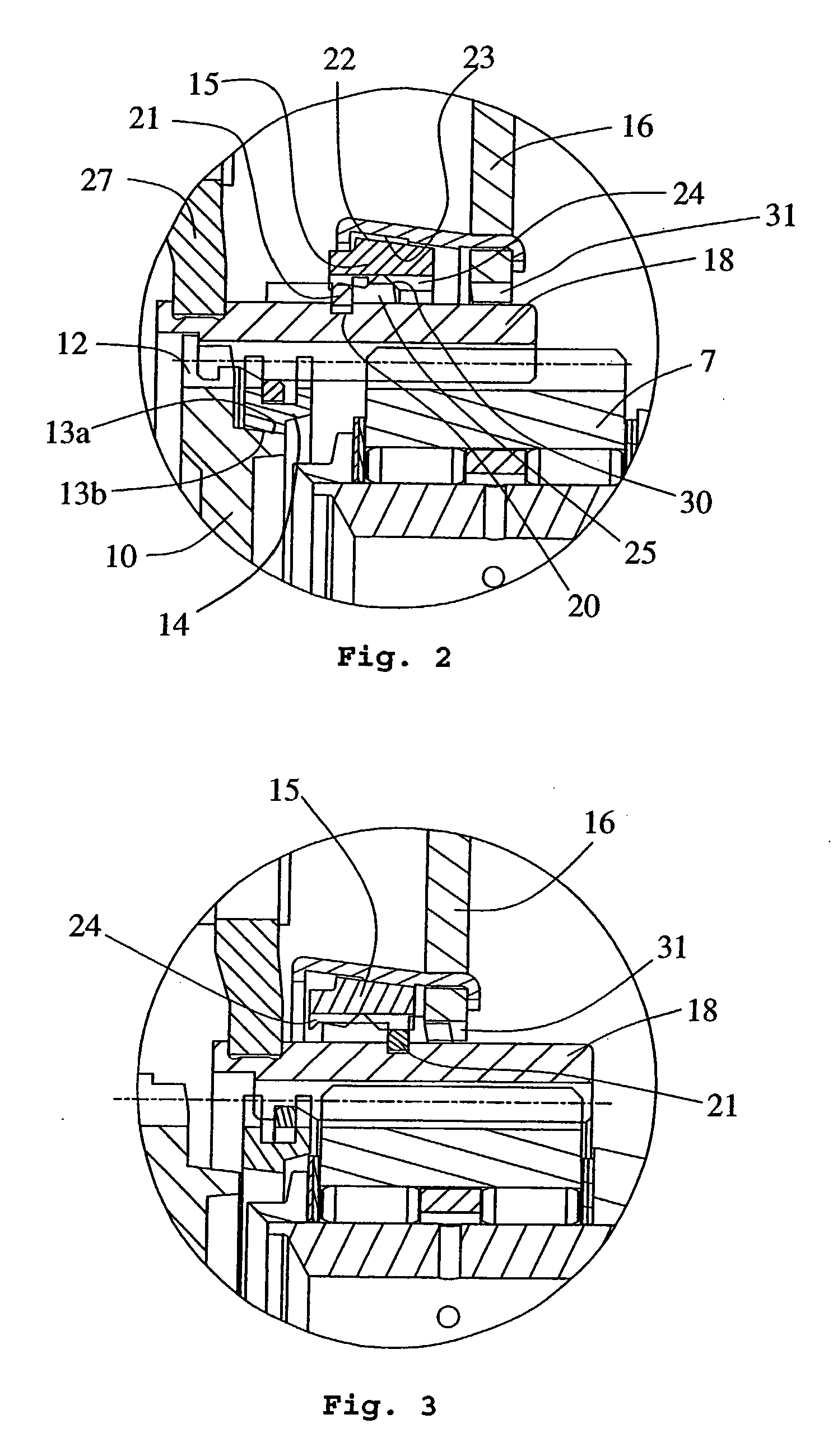
[0010] The following important advantages are achieved through the use of such an inventive arrangement. The shifting time, when shifting to a low-range gear, is shortened considerably. The shorter shifting time is achieved on account of the greater synchronizing torque which is obtained by virtue of the invention making it possible to arrange the friction surfaces of the synchronizing ring along a larger diameter, seen from the center line of the input and output shafts, that is to say the synchronizing ring is located coaxially outside the ring gear. Moreover, the overall length of the range gearbox is shortened further, and the space behind the second coupling ring becomes free and can be used for an auxiliary brake, for example a hydrodynamic retarder.
[0012] In a further advantageous second embodiment of the arrangement according to the invention, the internal teeth of the ring gear are helical teeth. The advantage of this is that a servo effect is obtained when the gear concerned is engaged. The helical teeth moreover provide quieter operation.

Problems solved by technology

Another disadvantage of known art is that the overall length is in many cases too great.

Method used


Image

  • Gearbox for motor vehicles
  • Gearbox for motor vehicles
  • Gearbox for motor vehicles

Examples


Embodiment Construction

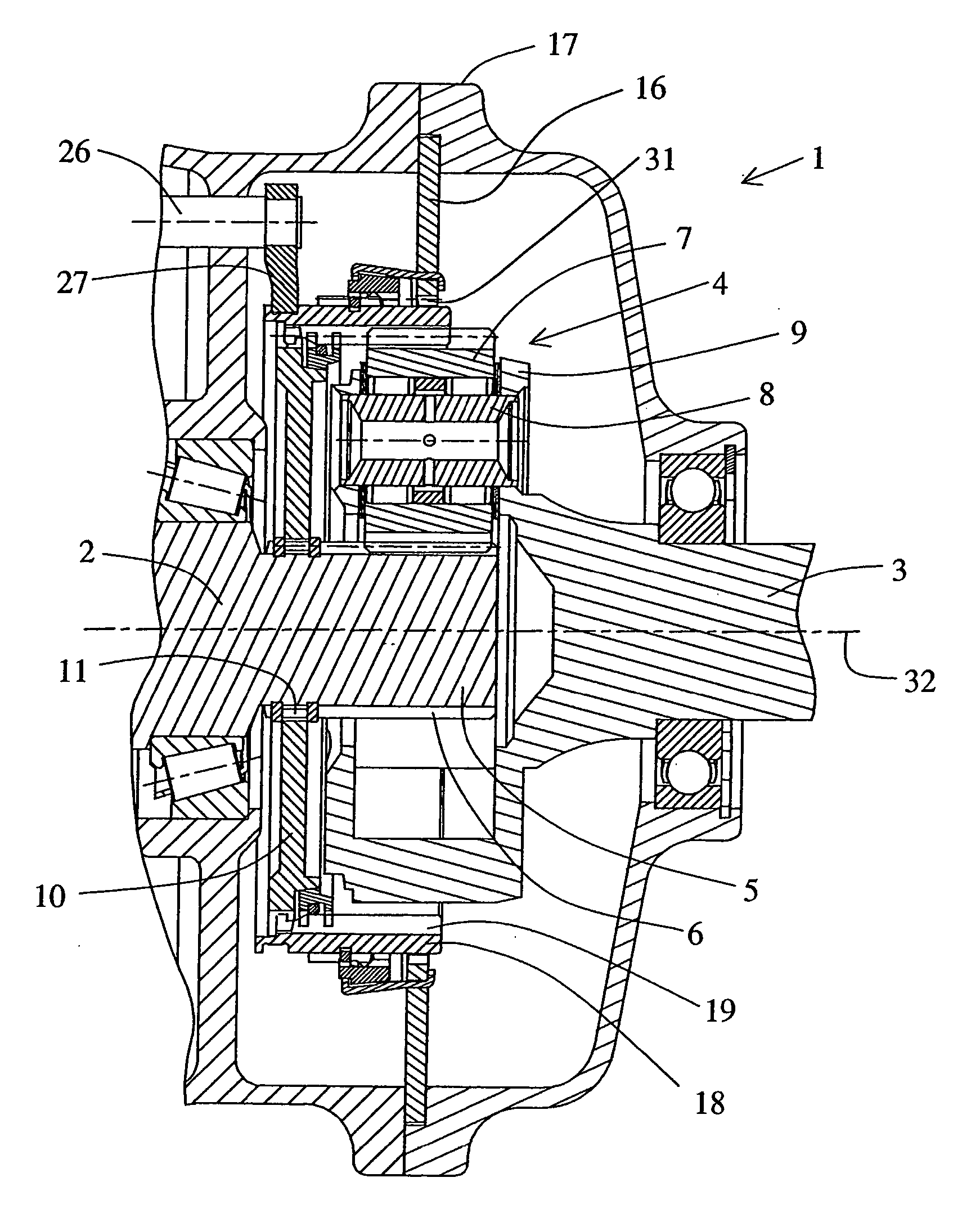
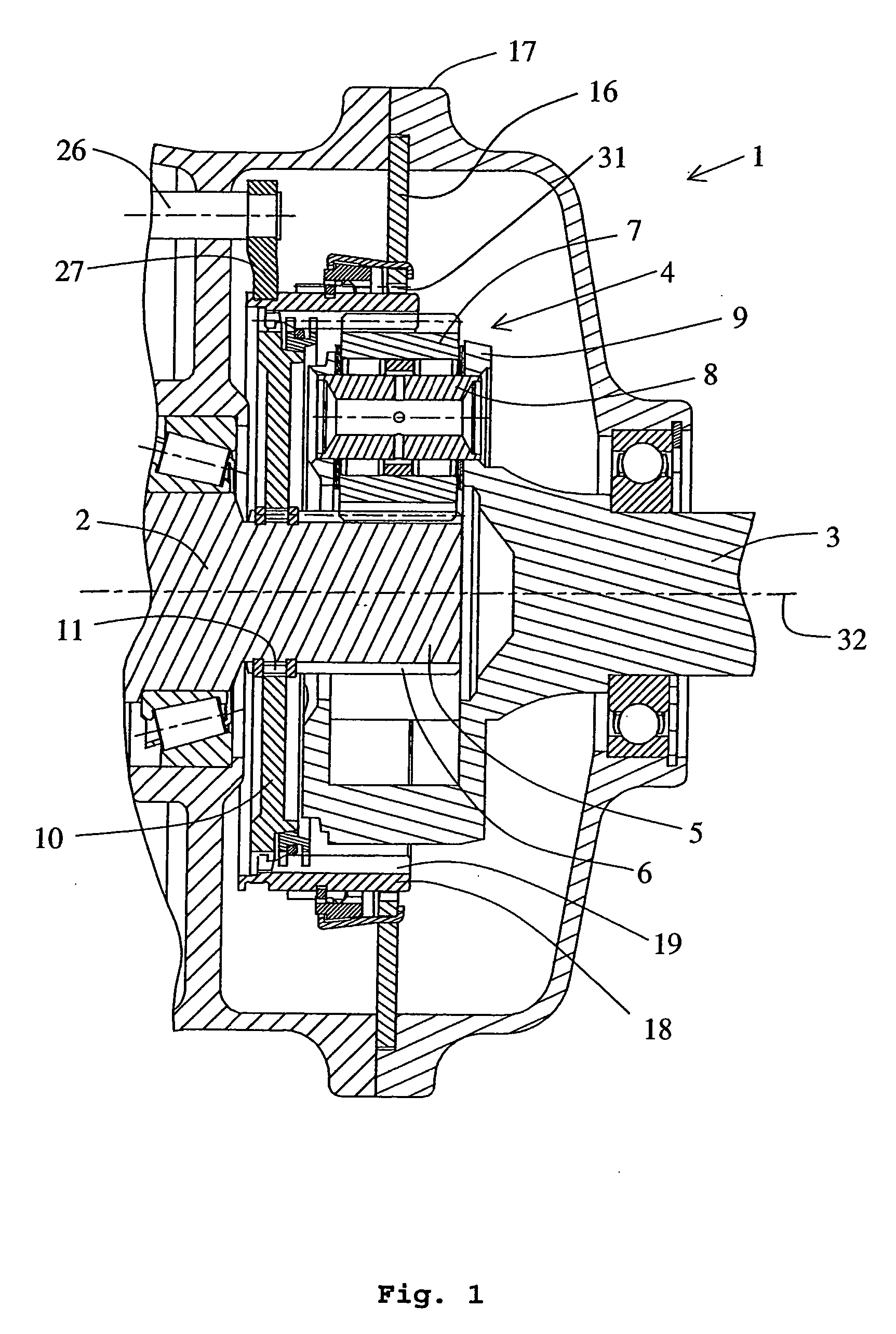
[0019]FIG. 1 shows a gearbox 1 configured according to the invention and which advantageously forms a range gearbox 1 intended to be connected to the output shaft of a basic gearbox (not shown) in a heavy-duty vehicle, for example a truck or bus. The range gearbox comprises a planetary gear 4.

[0020] The output shaft of the basic gearbox forms the input shaft 2 of the range gearbox 1. The planetary gear 4 is arranged between the input shaft 2 of the range gearbox and an output shaft 3 from the range gearbox. The output shaft forms part of a transmission (not shown) which transmits driving power to the driving wheels of the vehicle. The driving power is therefore supplied from the engine of the vehicle, via the basic gearbox, the range gearbox and also via a further transmission (not shown), to the driving wheels. A sun gear 5, forming part of the planetary gear 4, with external teeth 6, is mounted in a rotationally fixed manner on the input shaft. In the illustrative embodiment show...


PUM


Abstract

Method and arrangement for providing a range gearbox with planetary gear (1) for motor vehicles, intended to be connected to the output side of a basic gearbox. The ring gear (18) of the planetary gear is axially displaceable. The ring gear (18) can engage coupling rings (10, 16) alternatively. A synchronizing means (15) is intended to synchronize the rotational speed difference between the ring gear (18) and at least the coupling ring (16). The synchronizing means (15) and the coupling ring (16) are arranged coaxially outside the ring gear (18). A second means (25) for engaging the coupling ring (16) and a third means (25, 25b) for driving the synchronizing means (15) are arranged on the external side, seen radially, of the ring gear (18), and the synchronizing means (15) is arranged between the coupling ring (16) and the first means (27) for axial displacement of the ring gear (18).

Description

CROSS-REFERENCE TO RELATED APPLICATIONS [0001] The present application is a continuation patent application of International Application No. PCT / SE2004 / 000022 filed 13 January 2004 which was published in English pursuant to Article 21(2) of the Patent Cooperation Treaty, and which claims priority to Swedish Application No. 0300071-8 filed 14 January 2003. Said applications are expressly incorporated herein by reference in their entireties.FIELD OF THE INVENTION [0002] The present invention relates to a gearbox for motor vehicles, which is arranged between a basic gearbox and a transmission leading to driving wheels, and in which the gearbox is intended to be capable of shifting between two gearings and thus, together with the basic gearbox, doubling the total number of gearing possibilities. BACKGROUND OF THE INVENTION [0003] In transmission systems for heavy-duty vehicles, for example trucks and buses, it is known to connect an extra gearbox to the basic gearbox of the vehicle for ...

Claims


Application Information

Patent Timeline
IPC IPC(8): F16H3/44B60KF16D23/06F16HF16H1/00F16H3/78F16H37/04
CPCF16H3/78F16H37/046
Inventor ALFREDSSON, SVERKER
Owner VOLVO LASTVAGNAR AB
Learn More