Voltage converter control apparatus and method

a voltage converter and control apparatus technology, applied in the direction of dynamo-electric converter control, process and machine control, instruments, etc., can solve the problems of increased inner resistance, increased power consumption due to inner resistance of the battery, and inability to supply a certain amount of power

Inactive Publication Date: 2007-02-08
TOYOTA JIDOSHA KK
View PDF7 Cites 8 Cited by
  • Summary
  • Abstract
  • Description
  • Claims
  • Application Information

AI Technical Summary

Benefits of technology

[0006] With control by a voltage conversion device according to another aspect of the present invention, a ratio range setting means sets a range of ratios each between a period with an upper switching element remaining in an ON state and a period with a lower switching element remaining in an ON state, or a ratio range, based on output characteristics of the power source corresponding to the condition of the power source, which is determined by the condition detection means, and a control means controls the ratio between the periods with the respective switching elements remaining in an ON state so as to remain within the ratio range set by the ratio range setting means. This arrangement enables more appropriate extraction of an output from the power source based on the output characteristics of the power source depending on the condition of the power source. Here, “output characteristics of a power source” refers to correlation between an output of the power source and a ratio between periods with the respective switching elements remaining in an ON state.

Problems solved by technology

However, there may be situations in which, depending on the condition of the battery, a battery cannot supply an amount of power corresponding to a load requiring output when, for example, the battery inner resistance has increased due to low battery temperature.
Were the DC / DC converter be, in such a case, given driving control simply such that an amount of power corresponding to a load requiring output is fed to the load, power consumption due to inner resistance of the battery may increase, resulting in a drop in power supplied to the load.

Method used


Image

  • Voltage converter control apparatus and method
  • Voltage converter control apparatus and method
  • Voltage converter control apparatus and method

Examples


second embodiment

[0055] In the following, a driving system 120 according to the present invention will be described.

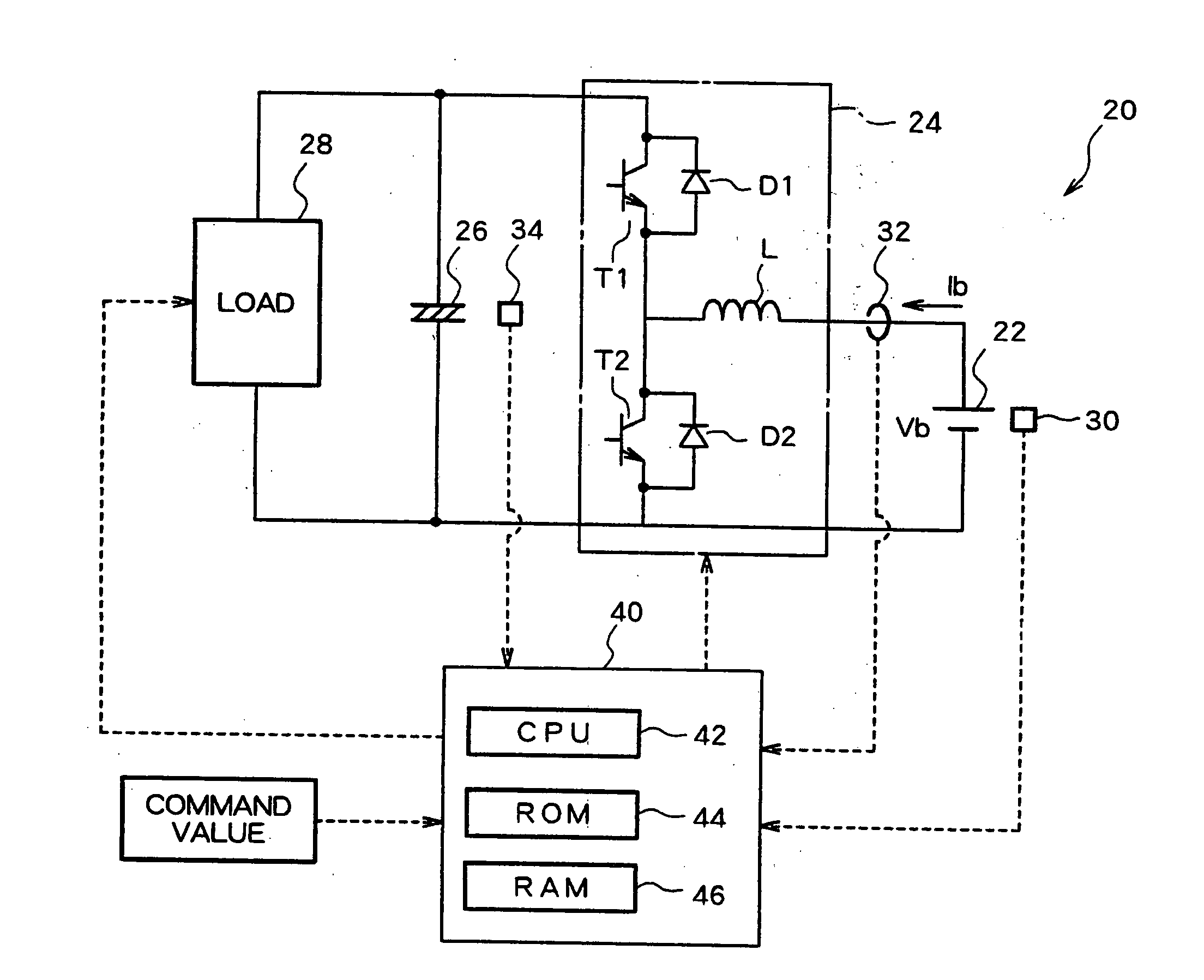
[0056]FIG. 8 is a schematic diagram showing a structure of a driving system 120 according to a second embodiment of the present invention. The hardware structure of the driving system 120 according to the second embodiment is identical to that of the driving system 20 in the first embodiment, with the notable exception that the driving system 120 does not have a current sensor 32, which is included in the driving system 20. Therefore, structural elements of the driving system 120 in the second embodiment, identical to those of the driving system 20 in the first embodiment are identified using similar reference numbers added by 100, and not explained again.

[0057]FIG. 9 is a flowchart of an example of a DC / DC converter driving control routine to be executed by the electronic control unit 140 of the driving system 120 in the second embodiment. That is, the driving system 120 in the secon...

first embodiment

[0074] Meanwhile, as a battery current Ib when the maximum output Bpmax is extracted from a battery is equal to a value Vbo / 2Rb, as described above with reference to the driving system 20 in the first embodiment, a battery voltage Vb at this time can be expressed using the expression (11) below.

Vb=Vbo / 2  (11)

[0075] From the fact that driving control of the DC / DC converter 24 is conducted such that a battery current Ib becomes less than or equal to a value Vbo / 2Rb in the driving system 10 of the first embodiment, it can be understood that driving control of the DC / DC converter must be conducted such that the battery voltage Vb becomes equal to Vbo / 2 or larger, in other words, a voltage drop due to the inner resistance of the battery becomes equal to a value Vbo / 2 or smaller in the driving system of the third embodiment. This is the significance of the determination as to whether or not the battery voltage Vb is greater than or equal to a value Vbo / 2. Therefore, the driving system in ...

fourth embodiment

[0078] In the fourth embodiment, a battery voltage Vb, a battery current Ib, and a battery electromotive voltage Vbo of the battery 22 are determined, similar to the above embodiments, and an inner resistance Rb of the battery 22 is always detected using the above-described expression (2). Further, the maximum permissible current Ibmax is determined based on at least one of the capacity of a current which can be supplied to the transistors T1, T2, which serve as switching elements of the DC / DC converter 24, or that which can be supplied to the battery 22, and stored in the ROM 44 or the like in the electronic control unit 40, for example. That is, the maximum permissible current Ibmax is determined by selecting either one, or a larger one, of the capacities of a current which can be supplied to the transistors T1, T2 or which can be supplied to the battery 22. It should be noted that any non-volatile memory may be employed for the ROM 44, with are writable EEPROM or a flash memory b...


PUM


Abstract

By using a target voltage Vc* of a capacitor connected to the output side of a DC / DC converter and a voltage Vb of a battery connected to the input side of the DC / DC converter, a duty ratio D as a drive instruction of the DC / DC converter is calculated. By using the voltage Vb, the electromotive force Vbo of the battery, and the charge / discharge current Ib of the battery, an internal resistance Rb is calculated. According to the internal resistance Rb and the electromotive force Vbo, the current value when the battery output becomes maximum is set as the upper limit value of the optimal current range IR, the DC / DC converter is driven / controlled by limiting the duty ratio D so that the current Ib is within the range of the optimal current range IR. Thus, it is possible to appropriately convert the battery input voltage.

Description

TECHNICAL FIELD [0001] The present invention relates to a control device and a voltage conversion method for a voltage conversion device, a recording medium, a program, a driving system, and a vehicle carrying the driving system. In particular, the present invention relates to a device having a reactor for temporary storage of energy based on a current from a power source, for converting a voltage of the power source, which is input using the reactor, into a desired voltage through switching of a switching element to output. BACKGROUND ART [0002] As a conventional driving system of the above-described kind, there is proposed a system comprising, for example, a battery serving as a power source of the driving system, a DC / DC converter for applying DC / DC conversion to an input voltage from the battery, a load having an inverter for converting an output from the DC / DC converter into a multi-phase AC current and a motor for rotation driving while receiving the multi-phase AC current fro...

Claims


Application Information

Patent Timeline
Patent Type & Authority Applications(United States)
IPC IPC(8): H02P5/00H02M3/155B60L11/18B60L15/20H02J7/00H02M3/157H02M7/529H02M7/5387
CPCB60L15/2045B60L2240/549H02J7/0065H02M3/157H02M7/529H02M7/53873H02M2001/0022Y02T10/7005Y02T10/7216Y02T10/7283Y02T10/92Y02T90/127Y02T90/14B60L7/14B60L11/1803B60L11/1812B60L15/007B60L2240/547B60L2210/10Y02T10/7072B60L53/22B60L50/51H02J2207/20Y02T10/64Y02T10/70Y02T10/72H02M1/0022H02M3/155Y02T90/12
Inventor OKAMURA, MASAKISATO, EIJI
Owner TOYOTA JIDOSHA KK
Why Eureka
Try Eureka