Sensor node

a node and sensor technology, applied in the field of sensors, can solve the problems of difficult to perform stable radio communication at a low electric power, and achieve the effect of improving measurement accuracy

Active Publication Date: 2007-02-08
MAXELL HLDG LTD
View PDF8 Cites 90 Cited by
  • Summary
  • Abstract
  • Description
  • Claims
  • Application Information

AI Technical Summary

Benefits of technology

[0006] Further, in the sensor node worn by a human body, when there is movement of the human body or a shift in wearing position, the precision of measuring biological information decreases.
[0013] Furthermore, when the sensor node is worn on the arm, light-emitting elements and a light-receiving element can be placed in a line substantially along the center of the arm, so the light-emitting elements and the light-receiving element can be placed along the blood vessel flowing through the arm. Consequently, in the case of measuring a pulsebeat, the sensor node can be brought into close contact with the blood vessel targeted for sensing. This enables stable sensing, which can enhance the measurement precision.

Problems solved by technology

Therefore, in order to keep stable communication performance while the electric power required for transmission is being reduced, it is difficult to perform stable radio-communication at a low electric power unless the arrangement of a radio circuit is taken into consideration.

Method used


Image

  • Sensor node
  • Sensor node
  • Sensor node

Examples


first embodiment

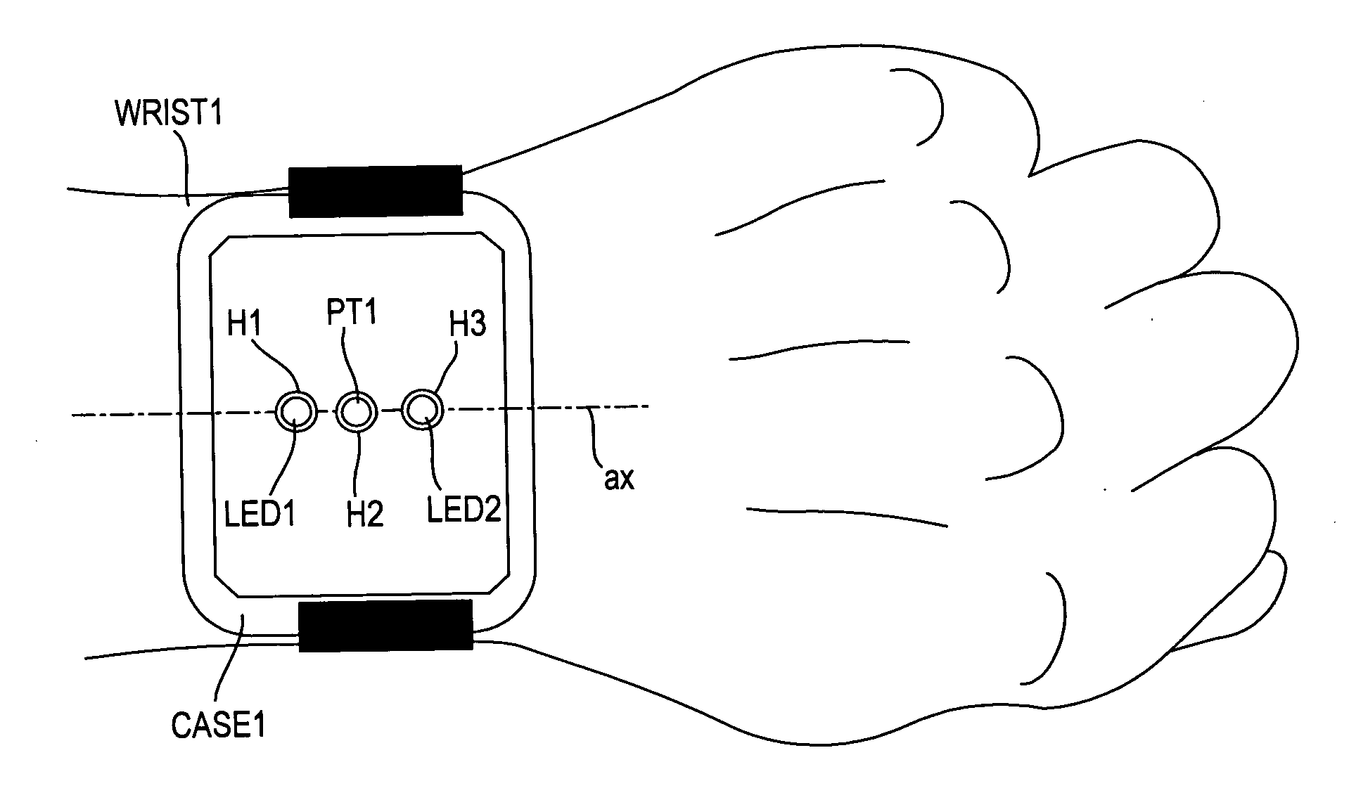
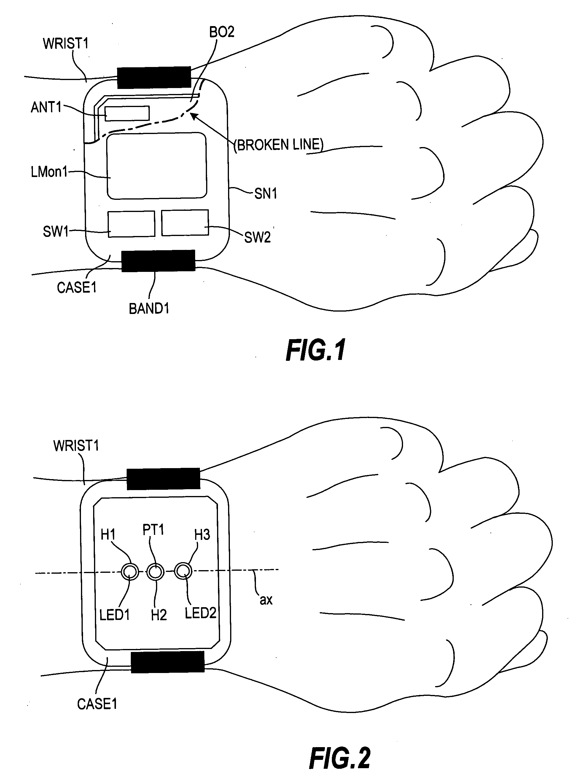
[0049]FIG. 1 is a front view showing an example in which this invention is applied to a wristband (or a wristwatch) sensor node SN1. The sensor node SN1 mainly measures a pulsebeat of a wearer.

[0050] At the center of a rectangular case CASE1 having four sides, a display unit LMon1 for displaying a message and the like is placed. As the display unit LMon1, a liquid crystal display unit or the like can be used. A band BAND1 for fixing the sensor node SN1 to the arm is attached from a first side, which is an end portion of the case CASE1 in the 12 o'clock direction of a wristwatch, to a second side opposed to the first side, which is an end portion of the case CASE1 in a 6 o'clock direction of the wristwatch. FIG. 1 shows a state where the sensor node SN1 is worn on the left arm (WRIST1). Hereinafter, the 12 o'clock direction of the wristwatch will be referred to as an upper portion of the case CASE1, and the 6 o'clock direction of the wristwatch will be referred to as a lower portion...

second embodiment

[0227]FIG. 33 shows a second embodiment, and the temperature sensor TS1 in the first embodiment measures humidity in addition to temperature.

[0228] In the case of the sensor node SN1 with the temperature / humidity sensor TS1 for sensing temperature and humidity mounted thereon, it is necessary that the indoor and outdoor air is sensed directly with the temperature / humidity sensor TS1. Therefore, the temperature / humidity sensor TS1 and the control circuit for the sensor node SN1 are mounted in the same environment as that of the indoor and outdoor. Condensation occurs on the surface of the control circuit due to the change in temperature and humidity in the vicinity of the control circuit, which causes the malfunction and failure.

[0229] Thus, ordinarily, the temperature / humidity sensor TS1 is mounted separately from the control circuit of the sensor node SN1. For example, the control circuit is mounted in a sealed case, and the temperature / humidity sensor is placed outside of the ca...


PUM


Abstract

To secure a stable radio-communication performance in a sensor node, the sensor node with a radio-communication circuit and a sensor, for transmitting data measured by the sensor through radio-communication, includes a first board BO2 on which an antenna ANT1 connected to the radio-communication circuit is placed, a case CASE1 containing the first board BO2, and a band that is attached to the case CASE1 so as to fix the case CASE1 to the skin. The antenna ANT1 is placed in an upper portion of the case CASE1, which corresponds to a 12 o'clock direction of a wristwatch.

Description

CLAIM OF PRIORITY [0001] The present application claims priority from Japanese application P2005-112477 filed on Apr. 8, 2005, the content of which is hereby incorporated by reference into this application. BACKGROUND OF THE INVENTION [0002] This invention relates to improvement of a sensor node with a radio-communication function usable on a sensor net, in particular, a sensor node wearable to a human body. [0003] Recently, a network system (hereinafter, referred to as a “sensor net”) has been studied, in which a small electronic circuit having a radio-communication function is added to a sensor to introduce various pieces of information in a real world into an information processing apparatus in real time. A wide range of applications have been considered for the sensor net. For example, there is a medical application, in which biological information such as a pulsebeat is always monitored by a small electronic circuit with a radio circuit, a processor, a sensor, and a battery int...

Claims


Application Information

Patent Timeline
Patent Type & Authority Applications(United States)
IPC IPC(8): G08B13/14
CPCH01Q9/0485H01Q1/273
Inventor AIKI, KIYOSHIKURIYAMA, HIROYUKIYAMASHITA, SHUNJOSHIMURA, TAKANORI
Owner MAXELL HLDG LTD
Why Eureka
Try Eureka