
Anchor device with an elastic expansion sleeve

Inactive Publication Date: 2007-02-08
BRUNEAU MARCELLIN
View PDF13 Cites 61 Cited by
  • Summary
  • Abstract
  • Description
  • Claims
  • Application Information

AI Technical Summary

Benefits of technology

[0026] In one of the embodiments of the invention, the anchoring device is characterized in that said rod is provided with at least two anchoring heads to increase the number of anchoring points along the drilled bore in the excavation wall, so that said anchoring device may resist to stronger loads.

Problems solved by technology

On the other hand, they do have important drawbacks, such that they do not allow their use in all circumstances.
In particular, they boast a mediocre performance when used with broken or soft rocks, and are sensitive to vibrations, i.e. they may lose their load following a ground blow or an adjacent blast.
Moreover, these bolts have a very small resistance to shear forces.
Indeed, if the shear forces are too high at the interface between the internal surface of the bore and the toothed blades of the shell, the internal surface of the bore may crumble, and the teeth of these blades may then release their grip from the internal surface of the bore.
This could be dangerous, since unless each bolt is individually tested to check if it is still loaded, a mounted bolt having lost its load may leave the impression to the workers that it is still operational whereas in fact it has become none at all.
On the other hand, installation of cemented bolts takes a lot of time and is expensive, requires use of a cement pump, and is messy and thus not user-friendly for the workers.
Moreover, installation of such bolts in vertical position, for example on the excavation top wall, is labour intensive, since it requires cement injection in a vertical bore.

Method used


Image

  • Anchor device with an elastic expansion sleeve
  • Anchor device with an elastic expansion sleeve
  • Anchor device with an elastic expansion sleeve

Examples


Embodiment Construction

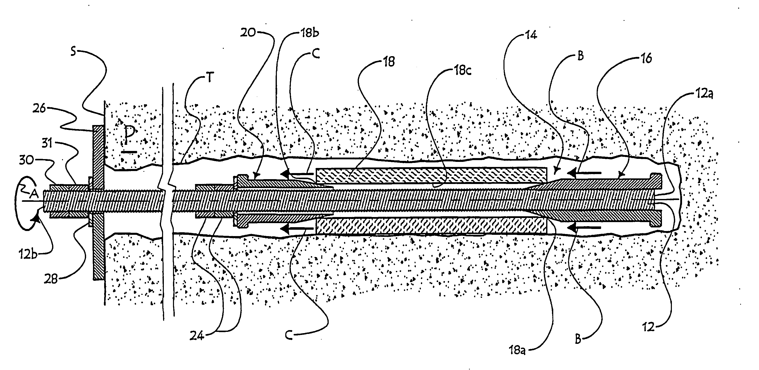
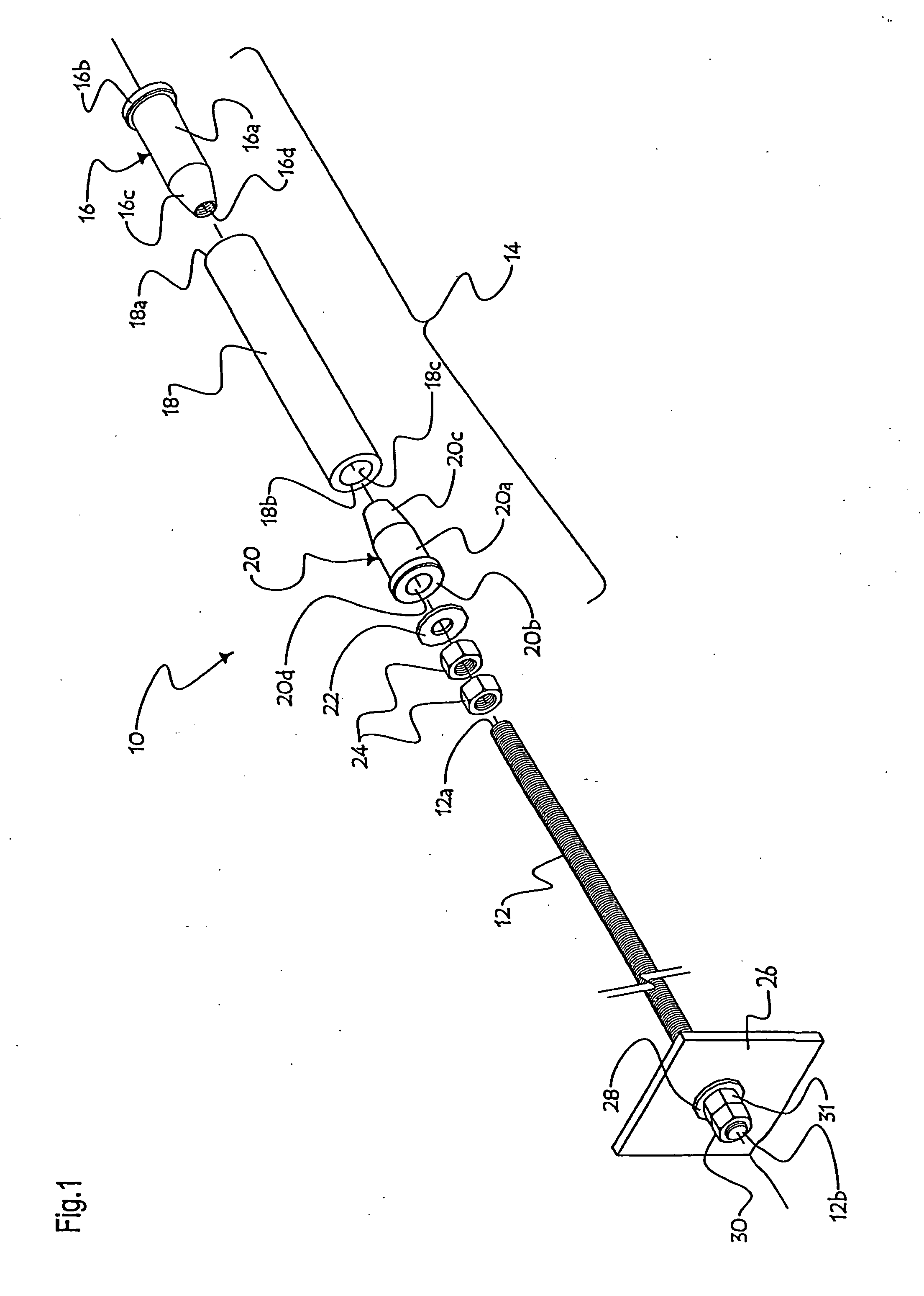
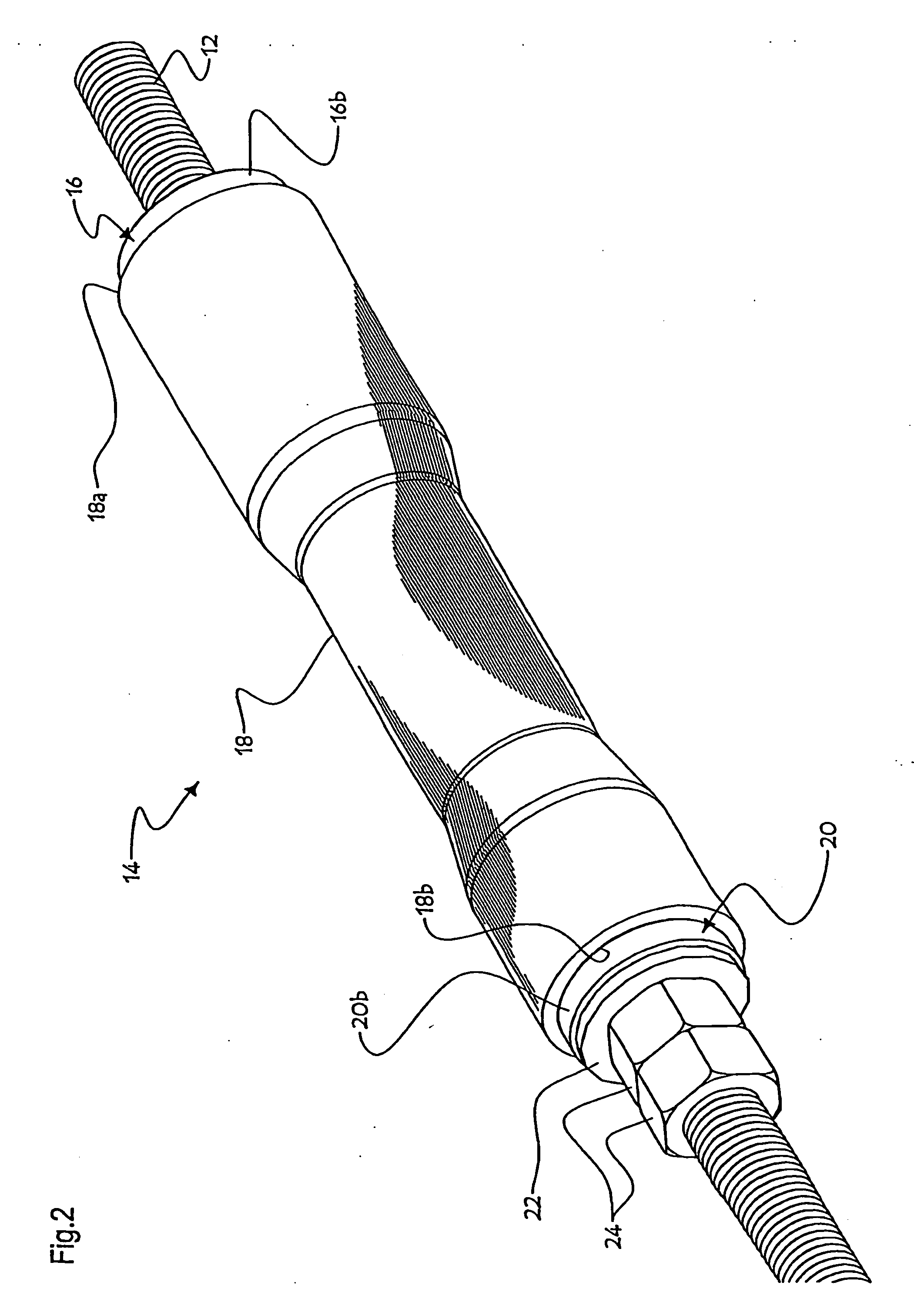
[0065]FIGS. 1-12 show several embodiments of the anchoring device of the present invention. Although these anchoring devices may be used on all sorts of walls requiring support, such as a concrete wall or the wall of a cliff, the present description, to facilitate reading, will deal only with their use to support a rocky excavation wall, for example in a mine.

[0066]FIGS. 1-3b show an anchoring bolt 10 according to one of the embodiments of the invention. Anchoring bolt 10 comprises a rigid threaded rod 12, also called stud bolt 12, and defining a distal end 12a and a proximal end 12b. Stud bolt 12 may have for example a length of ½ to 3 meters, depending for example on the purpose of the anchoring bolt 10.

[0067] An anchoring head 14 is mounted on the stud bolt 12, for example proximate its distal end 12a. This anchoring head 14 is destined to be engaged into a bore drilled into an excavation wall.

[0068] The anchoring head 14 comprises an expansion member having the shape of a tub...


PUM


Abstract

The invention relates to an anchor device, for stabilizing an excavation wall and to be inserted into a hole, bored in an excavation wall. Said anchor device comprises a rigid elongated rod which defines a distal end, to be inserted into the bored hole and a proximal end, opposed to the distal end, a support member, mounted on the rod in the vicinity of the proximal end thereof and provided for resting against an outer surface of the wall of rock and an anchor head, mounted on the rod and to be inserted into the hole, bored in the excavation wall. Said anchor head comprises a flexible expandable member, mounted on the rod, made of plastic and capable of radially expanding and stretching and an activating member, movably mounted on the rod, said activating member being capable of moving relative to the rigid rod and to the expandable member and capable of contacting the same in order to exert a pressure. For anchoring the anchor head into the excavation wall at the bored hole, the activating member and the expandable member are displaced relative to one another, such as to contact each other and to allow the activating member to exert a pressure upon the expandable member, in order to cause the radial expansion of at least one portion thereof, so that said portion of the expandable member makes frictional contact on a part of the inner surface, defining the hole bored in the excavation wall.

Description

CROSS REFERENCE DATA [0001] The present patent application claims priority based upon provisional patent application No. 60 / 514,004 filed in the United States of America on 27 Oct. 2003, in accordance with-the provisions of the Paris Convention.FIELD OF THE INVENTION [0002] The present invention relates to a supporting device for excavation walls, and more particularly to an anchoring bolt having an anchoring head comprising an elastic expansion sheath. BACKGROUND OF THE INVENTION [0003] Rock felling in a mine or any other type of underground excavation is usually performed by blasting up with explosive charges, and is followed by an extraction phase during which the thus felled rocks are removed from the working site. Miners must thereafter purge the excavation walls, i.e. generate the fall of rock blocks that have a tendency to detach therefrom, for example with a scaling bolt. After that, the stability of the thus formed shaft walls (of the tunnel, or of the chamber), must be con...

Claims


Application Information

Patent Timeline
IPC IPC(8): E21D21/00
CPCE21D21/0026E21D2021/0073E21D21/004E21D21/0033E21D21/0073E21D21/00
Inventor BRUNEAU, MARCELLIN
Owner BRUNEAU MARCELLIN
Learn More