Loader boom arm

a technology for loading booms and loaders, which is applied in the direction of soil shifting machines/dredgers, lifting devices, thin material processing, etc., can solve the problems of limiting the maximum height elevation and forward extension of the loader boom arm, and affecting the operation of loaders. the effect of reducing the loader loader loader loader loader loader loader loader loader loader loader loader loader loader loader loader

Inactive Publication Date: 2007-02-08
TUBE LINE MFG
View PDF15 Cites 32 Cited by
  • Summary
  • Abstract
  • Description
  • Claims
  • Application Information

AI Technical Summary

Benefits of technology

[0011] The upper arm functions as a lever having a fulcrum at the second pivot point, wherein the lever comprises a lever arm portion and a resistance arm portion, the lever arm portion being pivotally coupled to the link arm. In a preferred embodiment, the lever arm portion extends backwardly towards the lower arm from the second pivot point, and the resistance arm extends forwardly from the second pivot point to the free end of the upper arm, and the link arm pulls downwardly on the lever arm portion of the upper arm as the lower arm is raised, thereby causing the resistance arm portion of the upper arm to pivot upwardly relative to the lower arm.

Problems solved by technology

However, the use of a fixed angle boom arm limits the maximum height elevation and forward extension of the boom arm.
This limitation restricts where an operator can place material using the bucket, making some remote locations inaccessible to the operator.
However, the boom arms for these loaders tend to be significantly larger, more cumbersome, and more expensive than the boom arms for traditional small loaders for tractors.
The major drawback of this type of loader boom arm is that the lower and upper arms must be controlled independently using two different controls.
Simultaneous movement of both arms is further complicated by having the upper arm rotating relative to the motion of the lower arm.
The added complication of operating all three device independently means that more experienced and highly trained workers are required to operate large excavators.
Even then, very few operators can master the precise art of moving the three devices simultaneously.
Another problem with conventional loaders is the design of self leveling linkage assemblies that maintain a level bucket during raising and lowering of a boom arm.
Due to its high profile, the rod may obstruct an operator's view, preventing accurate use of the boom arm and bucket.
Furthermore, since the rod extends along the entire length of the boom arm, it requires a substantial amount of material, which is undesirable from a manufacturing and cost perspective.

Method used


Image

  • Loader boom arm
  • Loader boom arm
  • Loader boom arm

Examples


Embodiment Construction

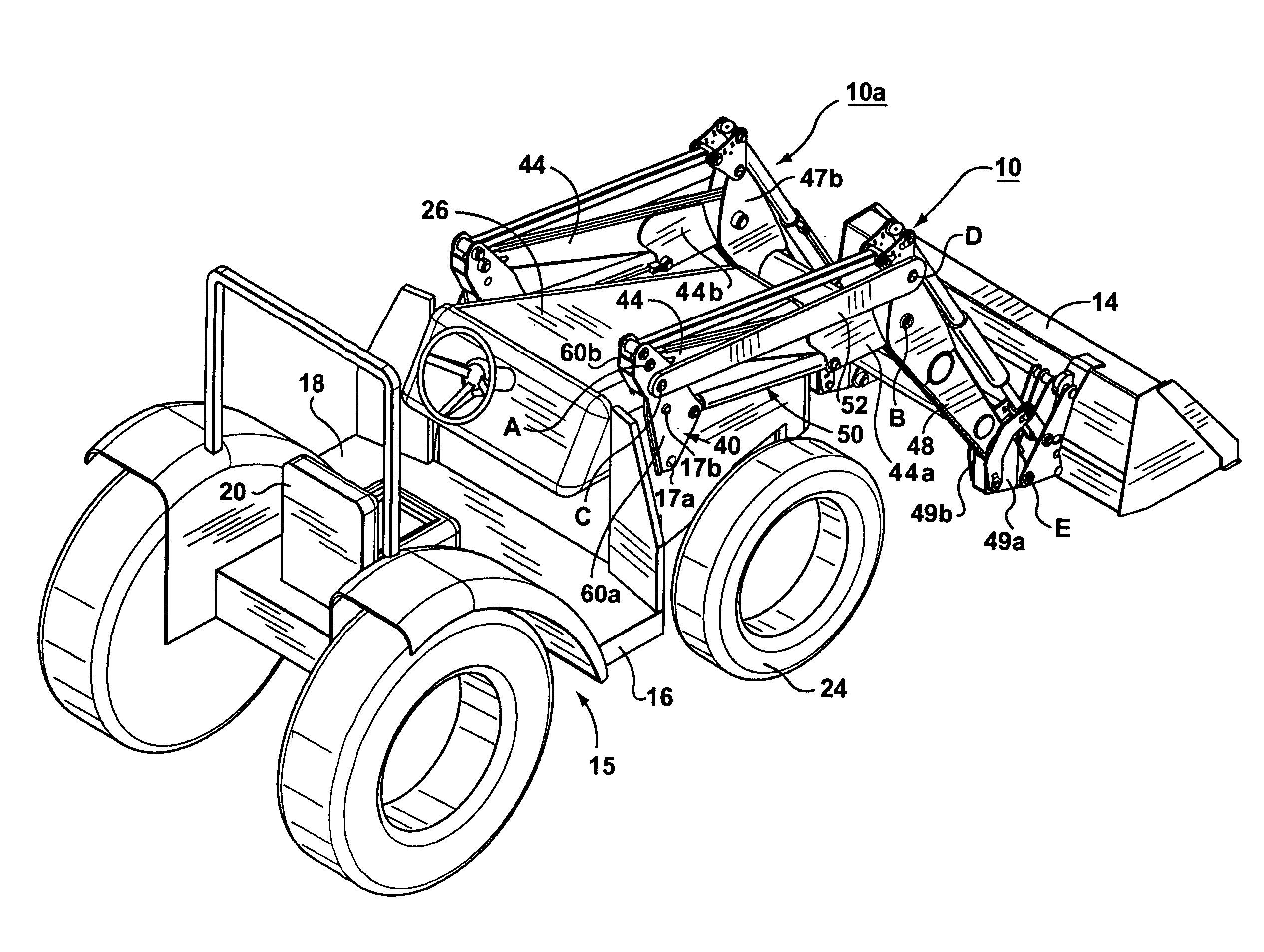
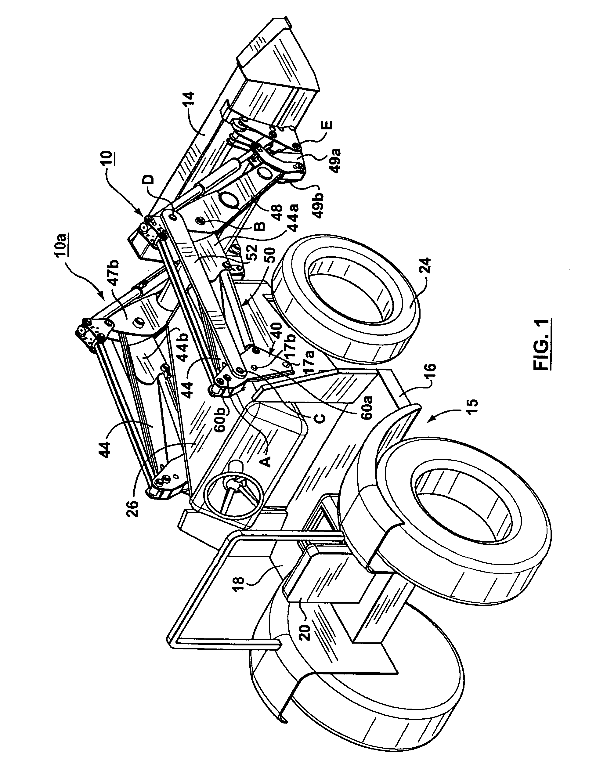
[0030] Referring to FIG. 1, illustrated therein is a pair of loader boom arms 10, 10a made in accordance with the subject invention, shown connected to a bucket 14 and mounted on a tractor 15 having a frame 16, driver's compartment 18 with seat 20, front tires 24 and engine compartment 26. Boom arms 10 and 10a are attached to frame 16 on laterally disposed sides of engine compartment 26. Bucket 14 is pivotally attached to the free ends of boom arms 10 and 10a at pivot point E. Orientation of boom arms 10 and 10a is such that bucket 14 extends forward from the front face of the tractor 15 so as to allow operation of the bucket 14 on material that is located in front of tractor 15. In operation, an operator sitting in seat 20 can drive tractor 15, move boom arms 10 and 10a and control bucket 14.

[0031] Boom arm 10a is a mirror image of boom arm 10, and unless otherwise stated, the components of boom arm 10a are the same as the components of boom arm 10. Boom arms 10, 10a operate in co...


PUM


Abstract

A loader boom arm for a material handling vehicle used in the agricultural or construction industries includes a post attachable to the vehicle, a lower arm pivotally connected to the post, an upper arm pivotally connected to the lower arm, a pivoting mechanism coupled to the post and the lower arm, and a link arm pivotally connected to the post and to the upper arm. The boom arm is raised and lowered in an angular direction of rotation by pivoting the lower arm about the post using the pivoting mechanism. As the lower arm is pivoted, the link arm causes the upper arm to pivot relative to the lower arm such that the upper arm pivots further in the direction of angular rotation than the lower arm, thus changing the angle between the lower arm and upper arm. The boom arm also preferably includes a low profile self leveling linkage assembly for maintaining the levelness of a bucket during raising and lowering of the boom arm, having a control arm pivotally connected to the lower arm, a rotator link pivotally connected to the upper arm at a leveling fulcrum, and an output arm pivotally connected to the rotator link and pivotally connectable to a work implement. The subject loader boom arm allows an operator to move material in a bucket attached to the boom arm to locations of higher elevation and further reach than typically available with conventional boom arms.

Description

RELATED APPLICATION [0001] This application is a continuation-in-part of application Ser. No. 11 / 186,887 filed on 22 Jul., 2005.FIELD OF THE INVENTION [0002] The present invention relates to loader boom arms for material handling vehicles, and in particular, to loader boom arms for tractors and other small vehicles used in the agricultural and construction industries. BACKGROUND OF THE INVENTION [0003] Material handling vehicles with boom arms and buckets are used in the construction and agricultural industries to move material such as earth. An operator will use the boom arm to raise the bucket off the ground so that the material can be placed in a dump truck or other location. Often the desired location is at a substantial height above ground and a considerable distance in front of the loader. [0004] Conventional loaders for tractors typically comprise a two-piece boom arm having a lower arm pivotally connected to the frame of the tractor and an upper arm rigidly connected to the ...

Claims


Application Information

Patent Timeline
Patent Type & Authority Applications(United States)
IPC IPC(8): B66C23/00
CPCE02F3/34E02F3/432E02F3/422Y10S414/13
Inventor FREY, OSCAR
Owner TUBE LINE MFG
Why Eureka
Try Eureka