Conveyor assembly

a conveyor and assembly technology, applied in the direction of conveyor parts, mechanical conveyors, transportation and packaging, etc., can solve the problems of increasing the pressure of the product in front, increasing the inertia load every time, and products that cannot tolerate this pressur

Inactive Publication Date: 2009-09-15
CAMPBELL III WILLIAM ARTHUR
View PDF40 Cites 34 Cited by
  • Summary
  • Abstract
  • Description
  • Claims
  • Application Information

AI Technical Summary

Benefits of technology

[0004]Systems and methods in accordance with the present invention eliminate the need for a moving support for the conveyors and the need for a system to take up and let out the belts. The receiving and discharge conveyors each include one or more round belts. The receiving and discharge belts are located so that they overlap and are interlaced. The receiving belts are at a slightly higher elevation on the receiving end of the system, and the discharge belts are at a slightly higher elevation on the discharge end. Both sets of belts pass through a movable carriage. This carriage guide

Problems solved by technology

Holding product behind a physical gate, however, allows the conveyor to slide under the back log of product, and each product creates more pressure on the products in front of it.
Some products can not tolerate this pressure or in the case of some soft or sticky products can not stand any product to produc

Method used


Image

  • Conveyor assembly
  • Conveyor assembly
  • Conveyor assembly

Examples


Embodiment Construction

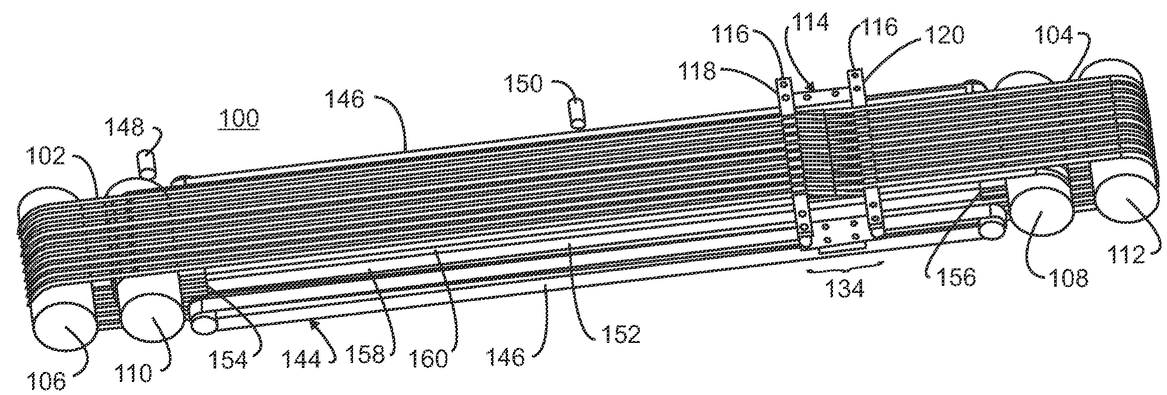
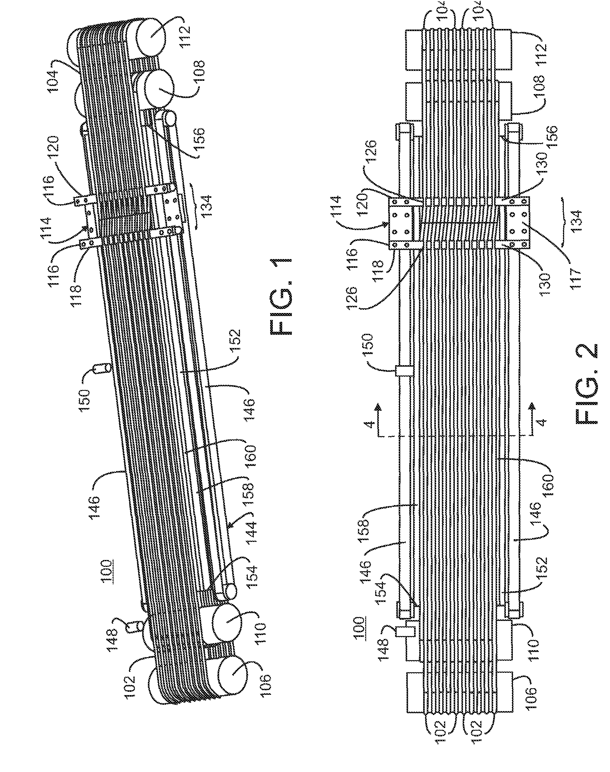
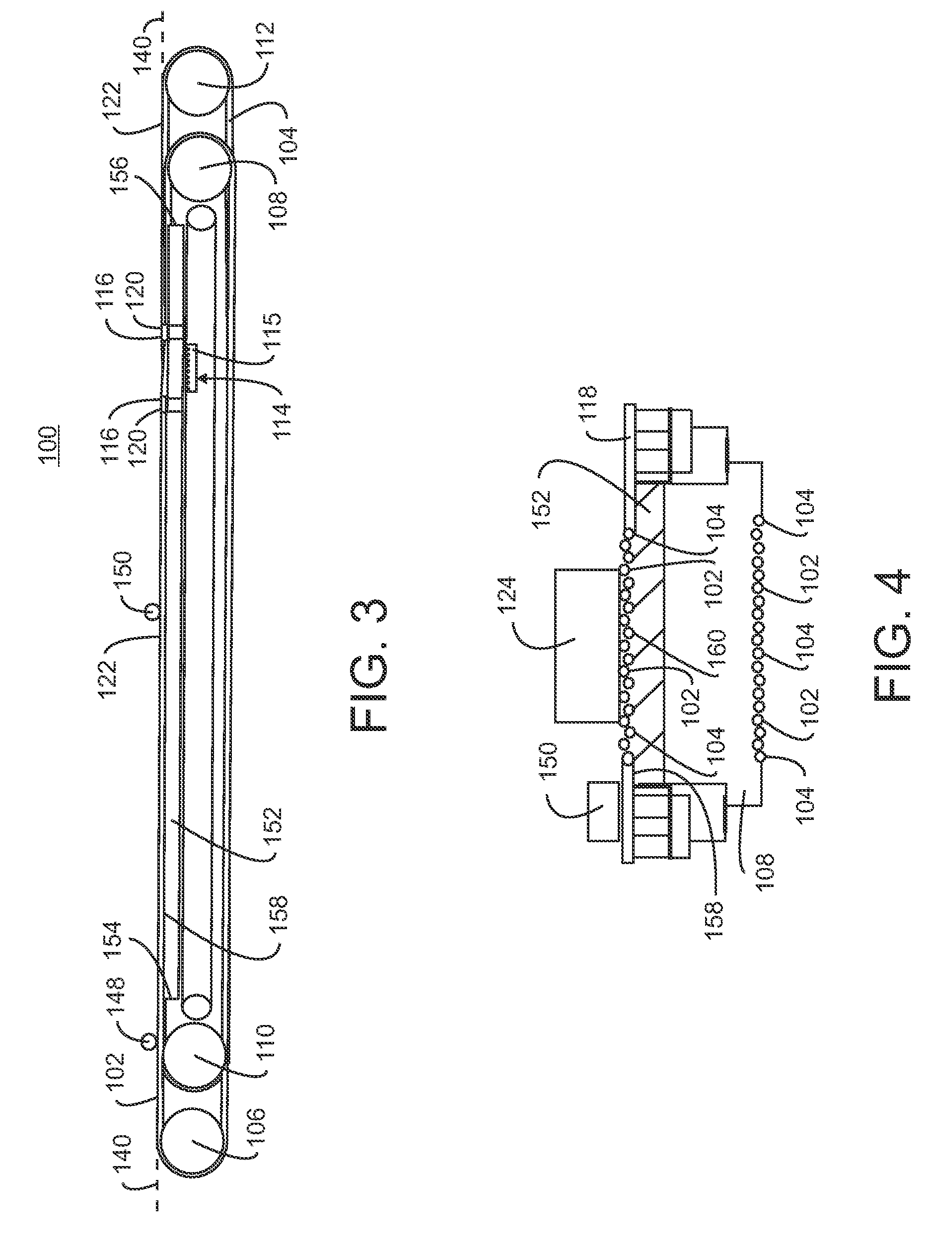
[0024]Referring initially to FIGS. 1-3, exemplary embodiments of the present invention are directed to a conveyor assembly 100. The conveyor assembly moves manufactured products, for example baked goods or confections, between stations or processes in a manufacturing facility. In addition to moving products between two stations or processes, the conveyor assembly compensates for any differences in speed between the two processes, acting as a buffer or accumulator in the system. The conveyor assembly includes at least one first conveyor belt 102, referred to as a receiving belt, and at least one second conveyor belt 104, referred to as the discharge belt. Although the present invention can utilize just two belts, a single first conveyor belt and a single second conveyor belt, preferably, the conveyor assembly includes a plurality of first conveyor belts 102 and a plurality of second conveyor belts 104. Suitable types and materials for the conveyor belts are known and available in the...


PUM


Abstract

A conveyor assembly is provided for accumulating and discharging a column of evenly spaced items. The conveyor assembly includes a receiving conveyor, a discharge conveyor and a belt guiding carriage. The receiving and discharge conveyors each include a plurality of round belts that are interlaced with the receiving belts being at a slightly higher elevation on the receiving end of the system and the discharge belts being at a slightly higher elevation on the discharge end. Both sets of belts pass through a movable carriage that guides the receiving belts from the upper elevation to the lower elevation and the discharge belts from the lower elevation to the upper elevation so that the receiving belts are at a higher elevation on the receiving end of the carriage and the discharge belts are at a higher elevation on the discharge end of the carriage.

Description

FIELD OF THE INVENTION[0001]The present invention relates to conveyor systems.BACKGROUND OF THE INVENTION[0002]For machines within a manufacturing process to operate properly, these machines require a steady and controlled rate of product coming to them. One of the easiest ways to accomplish this is to accumulate product on a conveyor behind some type of gating mechanism. Holding product behind a physical gate, however, allows the conveyor to slide under the back log of product, and each product creates more pressure on the products in front of it. Some products can not tolerate this pressure or in the case of some soft or sticky products can not stand any product to product contact.[0003]Previous attempts at solving the problem of a physical gating mechanism and the associated backlog pressure use a system composed of a receiving conveyor and a discharge conveyor connected by a moving transfer point. The receiving conveyor runs faster than the discharge conveyor. Therefore, product...

Claims


Application Information

Patent Timeline
IPC IPC(8): B65G15/10
CPCB65G15/105B65G47/31B65G21/14
Inventor CAMPBELL, III, WILLIAM ARTHUR
Owner CAMPBELL III WILLIAM ARTHUR
Why Eureka
Try Eureka