Communication portable terminal device

a terminal device and portable technology, applied in the direction of current supply arrangement, instruments, optical elements, etc., can solve the problems of failure to visually recognize the emission of light, difficult to visually know the call in the same manner as in the former case, and achieve the effect of uniform surface emission

Inactive Publication Date: 2007-02-08
PANASONIC CORP
View PDF4 Cites 14 Cited by
  • Summary
  • Abstract
  • Description
  • Claims
  • Application Information

AI Technical Summary

Benefits of technology

[0014] Accordingly, the light emitted from the light source can be fetched (incident) at an almost equal rate in various directions through the incident portion of the light transmitting member. Consequently, it is possible to implement a uniform surface emission in the light emitting unit without emitting a light partially to only a part of the light emitting unit.

Problems solved by technology

However, it is not preferable to make a sound depending on a place of use.
In some cases in which a small light emitting unit is provided to emit a light from a small area in the former method, for example, it is hard to visually recognize the emission of the light.
There is also a possibility that the light emitting operation might be known with a delay and a phone might be thus hung up before a response to a call from a partner or a calling state might be missed, resulting in a failure in calling.
On the other hand, in some cases in which the type for causing the display unit to emit a light in the latter method has such a structure as to cause a part of the display unit to locally emit a light, it is hard to visually know the call in the same manner as in the former case.
In the case in which the light emitting unit has a large area, however, it is hard to obtain a sufficient amount of a light emitted in a light emitting operation to be carried out by one light source (LED).
Corresponding to the use of the light sources, however, a built-in battery is consumed greatly with an increase in a consumed power.

Method used


Image

  • Communication portable terminal device
  • Communication portable terminal device
  • Communication portable terminal device

Examples


Embodiment Construction

[0023] An embodiment of the invention will be described below in detail with reference to the accompanying drawings.

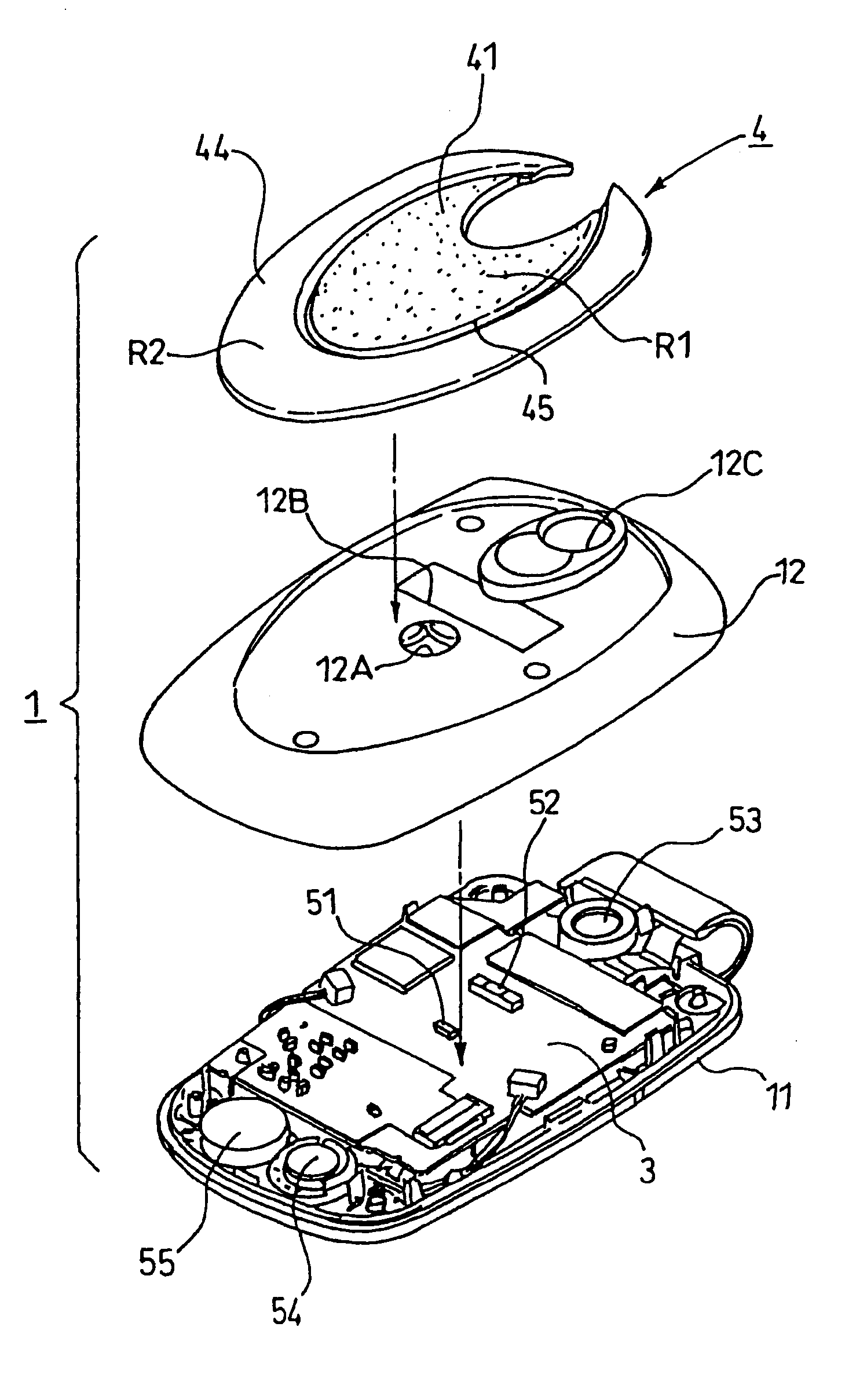
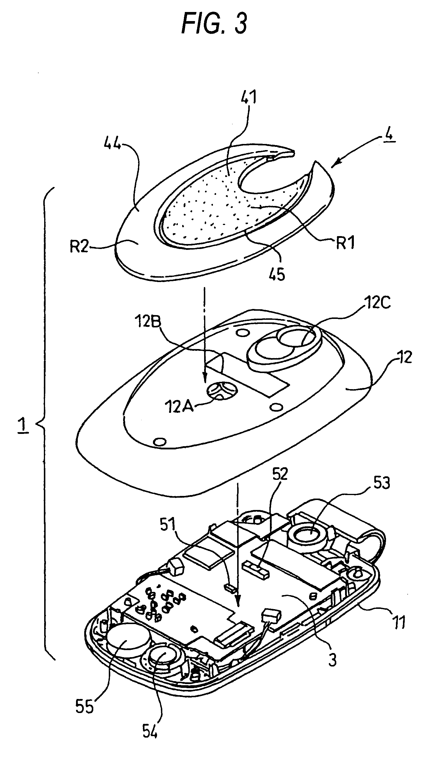
[0024]FIG. 1 shows a cell phone of a folding type according to the embodiment of the invention. The cell phone has such a structure that a housing portion includes an upper housing 1 provided with a liquid crystal display unit 2 (see FIG. 4) on one surface which is not shown (which will be hereinafter referred to as an inner side surface), a lower housing provided with an operating key on one surface which is not shown (which will be hereinafter referred to as an inner side surface), and a hinge portion H for rotatably coupling these housings to each other.

[0025] As shown in FIGS. 2 and 3, the upper housing i has a schematic structure as to include an inner case 11 (corresponding to an opposed portion to a lower housing when the upper and lower housings 1 are folded and closed), an outer case 12, and a light emitting panel 4 to be fixed to the outer case 12, and the ...


PUM


Abstract

It is an object of the invention to emit a light in order to brighten a large area by a single light source. The invention provides a communication portable terminal device including a single LED (51) disposed in an upper housing (1) and a light emitting panel (4) disposed on the upper housing (1) for emitting a light like a plane by a light emitted from the LED (51), the light emitting panel (4) including a light transmitting member (40) having an incident plane (42) on which the light emitted from the LED (51) is incident and a light emitting plane (44) for emitting a light like a plane by the light emitted from the LED (51), and a reflecting film (41) and a print film (43) provided on a surface and a back face of the light transmitting member (40) for reflecting the light emitted from the LED (51) and incident on the incident plane (42) of the light transmitting member (40) many times between the surface and the back face, thereby guiding the light to the light emitting plane (44).

Description

TECHNICAL FIELD [0001] The present invention relates to a communication portable terminal device, and more particularly to a communication portable terminal device capable of giving a notice that there is a call from a calling destination or an incoming call of a mail through a light emission in a wide area. BACKGROUND ART [0002] In a cell phone, as is well known, it is possible to inform a user that there is a call from a calling destination or an incoming call of a mail through a ring or a ringer tone. However, it is not preferable to make a sound depending on a place of use. For this reason, a cell phone for giving a notice of a call and an incoming call through a vibration (a vibrator) in place of a sound has also spread widely. [0003] Moreover, there has also been known a cell phone including a light emitting unit having a light source in order to give a notice of a call and an incoming call through a light in place of the sound and the vibration. In particular, the notice of t...

Claims


Application Information

Patent Timeline
Patent Type & Authority Applications(United States)
IPC IPC(8): H04M1/00H04M1/02H04M1/22
CPCH04M1/0214H04M19/048H04M19/04H04M1/22
Inventor YAMADA, TAKUJUDAI, KANTASAWADA, YUICHI
Owner PANASONIC CORP
Why Eureka
Try Eureka