Backlight lamp device and liquid crystal display device

A technology of backlight and light-emitting part, which is applied to display devices, lighting devices, components of lighting devices, etc., can solve the problems of increasing the thickness of backlight devices, and achieve miniaturization, thickness reduction, and uniform surface lighting. Effect

Inactive Publication Date: 2008-12-17
ORMON CORP
View PDF7 Cites 0 Cited by
  • Summary
  • Abstract
  • Description
  • Claims
  • Application Information

AI Technical Summary

Problems solved by technology

At this time, in order to sufficiently mix the colors of the lights emitted from the three light emitting diodes to generate white light, it is necessary to ensure a sufficiently large distance from the light emitting diodes to the liquid crystal panel, so there is a problem that the thickness of the backlight device increases.

Method used


Image

  • Backlight lamp device and liquid crystal display device
  • Backlight lamp device and liquid crystal display device
  • Backlight lamp device and liquid crystal display device

Examples


Embodiment Construction

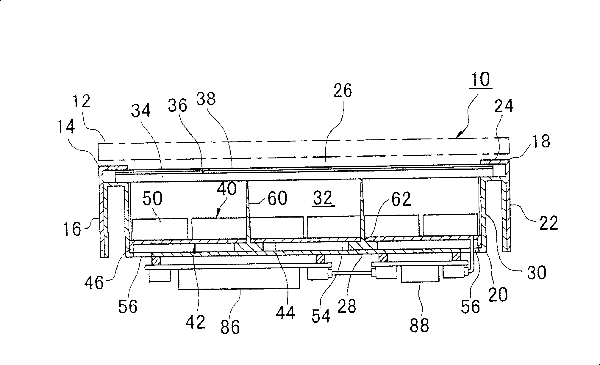
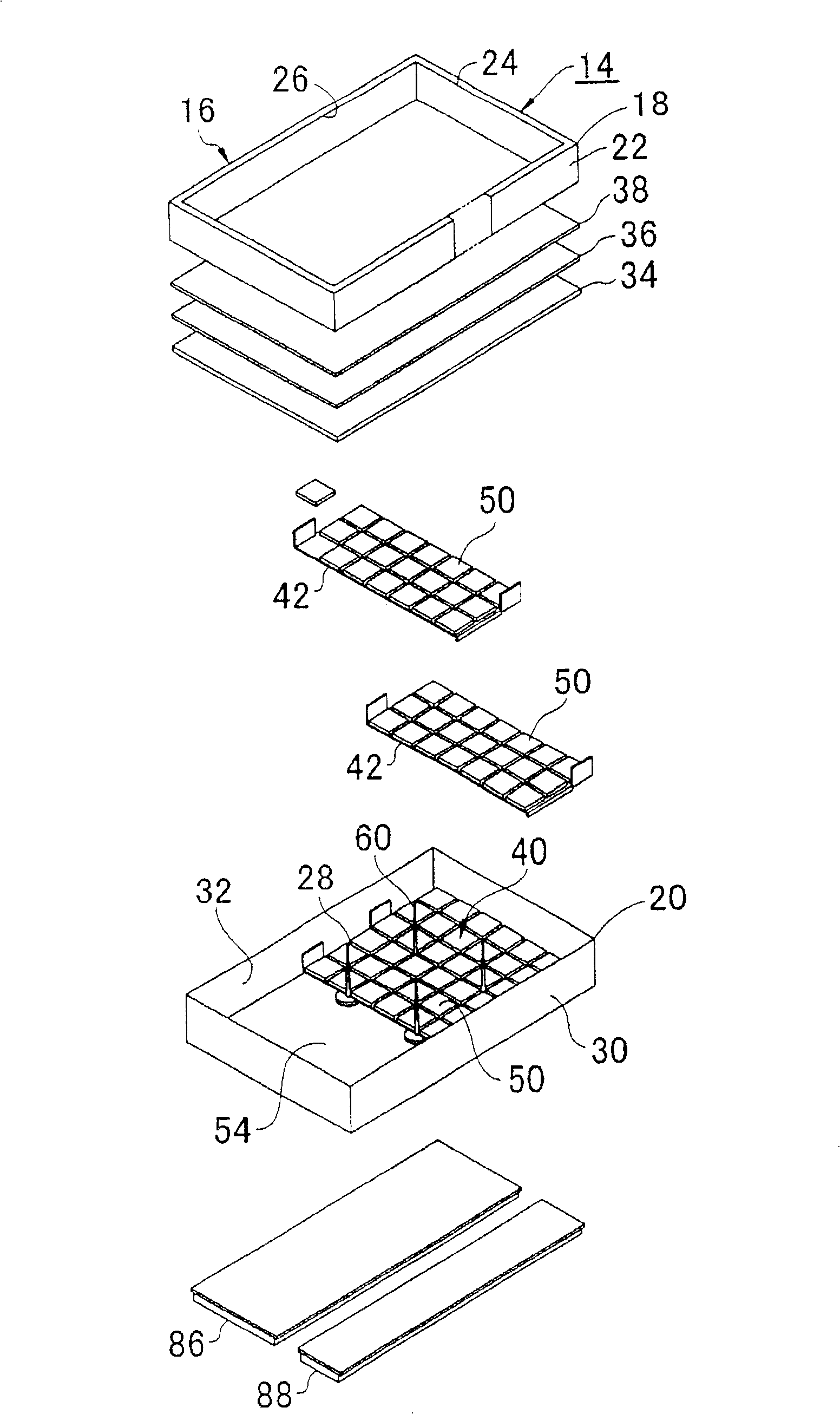
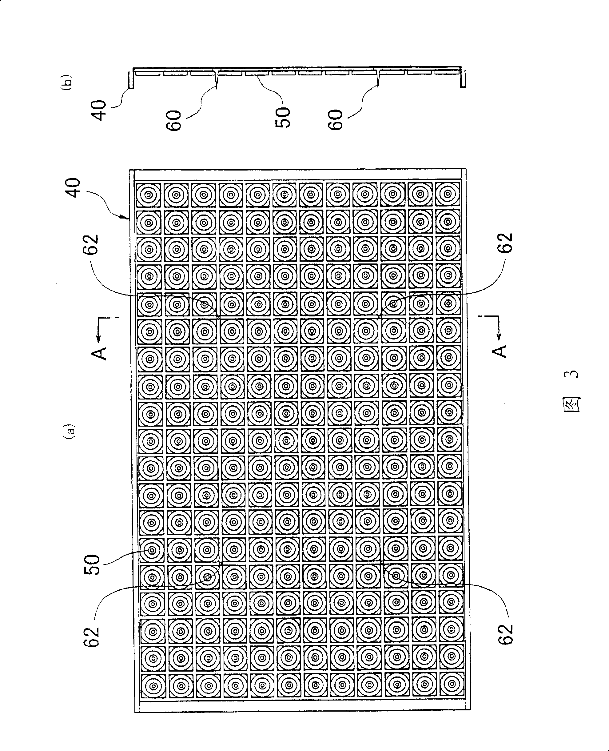
[0037] Hereinafter, the best mode for carrying out the present invention will be described with reference to the drawings. In addition, in the following description, terms indicating a predetermined direction (such as "up", "down", "right", "left") and other terms containing these terms (such as "above", "below" , "right side", "left side"), however, these terms are for easy understanding of the present invention with reference to the drawings, and the technical scope of the invention is not limited by these terms. Therefore, the embodiment of the present invention described below is turned upside down, or rotated to a predetermined angle (eg, 90 degrees) in any direction (eg, clockwise or counterclockwise) also falls within the technical scope of the present invention.

[0038] figure 1 It is a cross-sectional view of a liquid crystal display device. The illustrated liquid crystal display device 10 has a liquid crystal panel 12 and a backlight device 14 disposed behind the ...


PUM


Abstract

A thin liquid crystal display device and a backlight device. The backlight unit (14) has a diffuser sheet (36) for diffusing light and a light source unit (40) arranged behind the diffuser plate, and the diffuser plate diffuses light emitted from the light source unit to obtain surface emission. The light source unit has a plurality of light emitting units (50) arranged along a plane parallel to the diffusion plate. The plurality of light-emitting parts respectively include: a base material (66) made of a light-transmitting material having an emission surface (68) opposite to the diffusion plate; a light-emitting element (72) embedded in the base material; The reflective surface (77) and the reflective part (70) that guide the light from the entire area or approximately the entire area of ​​the above-mentioned emitting surface to the diffusion member vertically or approximately vertically.

Description

technical field [0001] The present invention relates to a backlight device used in a liquid crystal display device and a liquid crystal display device having the backlight device. Background technique [0002] A liquid crystal display device used as a display device of a computer requires a lighting device called a backlight device because liquid crystal itself is non-luminescent. As a light source of such a backlight device, a small-diameter fluorescent tube such as a cold cathode tube is generally used at present. As a method of arranging cold cathode tubes, there are known an edge light method in which fluorescent tubes are arranged along the edge of a liquid crystal panel and a direct method in which a plurality of fluorescent tubes are arranged behind a liquid crystal panel (see Patent Document 1). Comparing these two methods, the directly below method has higher light utilization efficiency than the edge light method because the light emitted from the fluorescent tube...

Claims


Application Information

Patent Timeline
Patent Type & Authority Patents(China)
IPC IPC(8): G02F1/1335F21V7/00F21V7/04H01L33/60
CPCF21Y2115/10G02F1/133603G02F1/133605G02F1/133606Y10S362/80
Inventor 吉田宪司铃木充博大场正利山田真幸
Owner ORMON CORP
Why Eureka
Try Eureka