Cable lock device for prosthetic and orthotic devices

Inactive Publication Date: 2007-02-08
ADA TECH
View PDF45 Cites 29 Cited by
  • Summary
  • Abstract
  • Description
  • Claims
  • Application Information

AI Technical Summary

Benefits of technology

[0015] The permanent magnet in the lever can be a rare earth magnet. In this configuration, the face of the magnet is covered by a diamagnetic material to provide a space between the magnetic member and a contacting electromagnet. The diamagnetic material can be an elastic, elastomeric, open or closed cell foamed, polymeric, and/or carbon-containing material or composites thereof. The material can provide shock absorption to prevent damage to the magnet from impacts against electromagnets as the lever moves between the first and second modes.
[0016] The electromagnetic two-state toggle configuration can provide a compact, energy efficient, and easily controlled single device. The unit can be simple, commonly using only three moving parts (including

Problems solved by technology

Users of voluntary opening and voluntary closing terminal devices are plagued by a number of problems.
In voluntary closing devices, the gripping digits in the terminal device are splayed open while the unit is at rest, making the unit susceptible to striking nearby objects, and people, as the user moves about.
In bo

Method used


Image

  • Cable lock device for prosthetic and orthotic devices
  • Cable lock device for prosthetic and orthotic devices
  • Cable lock device for prosthetic and orthotic devices

Examples


first embodiment

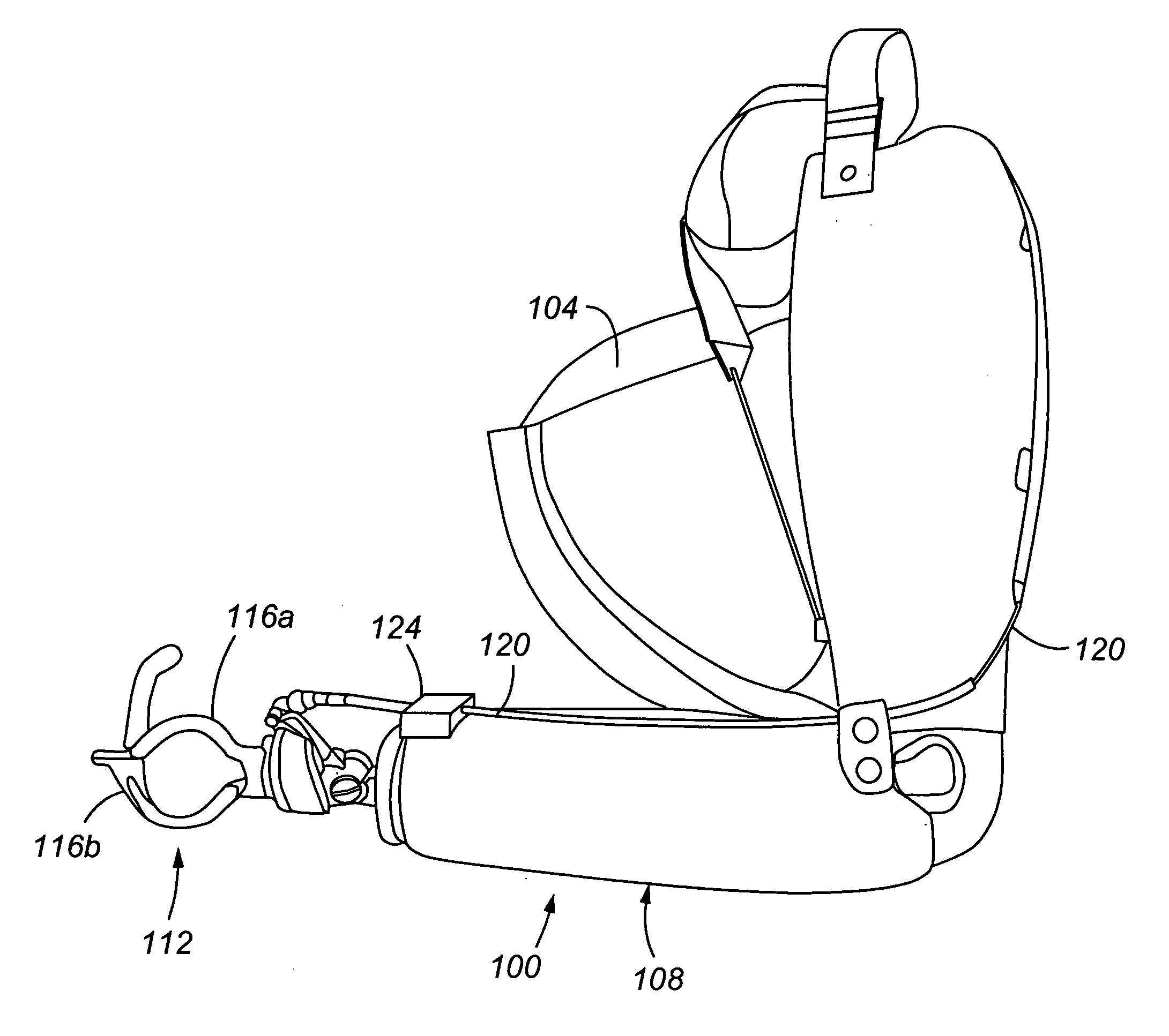
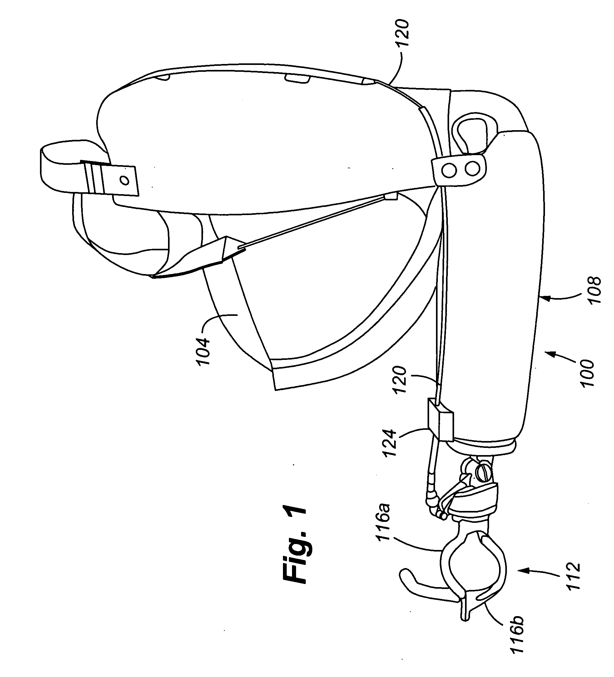
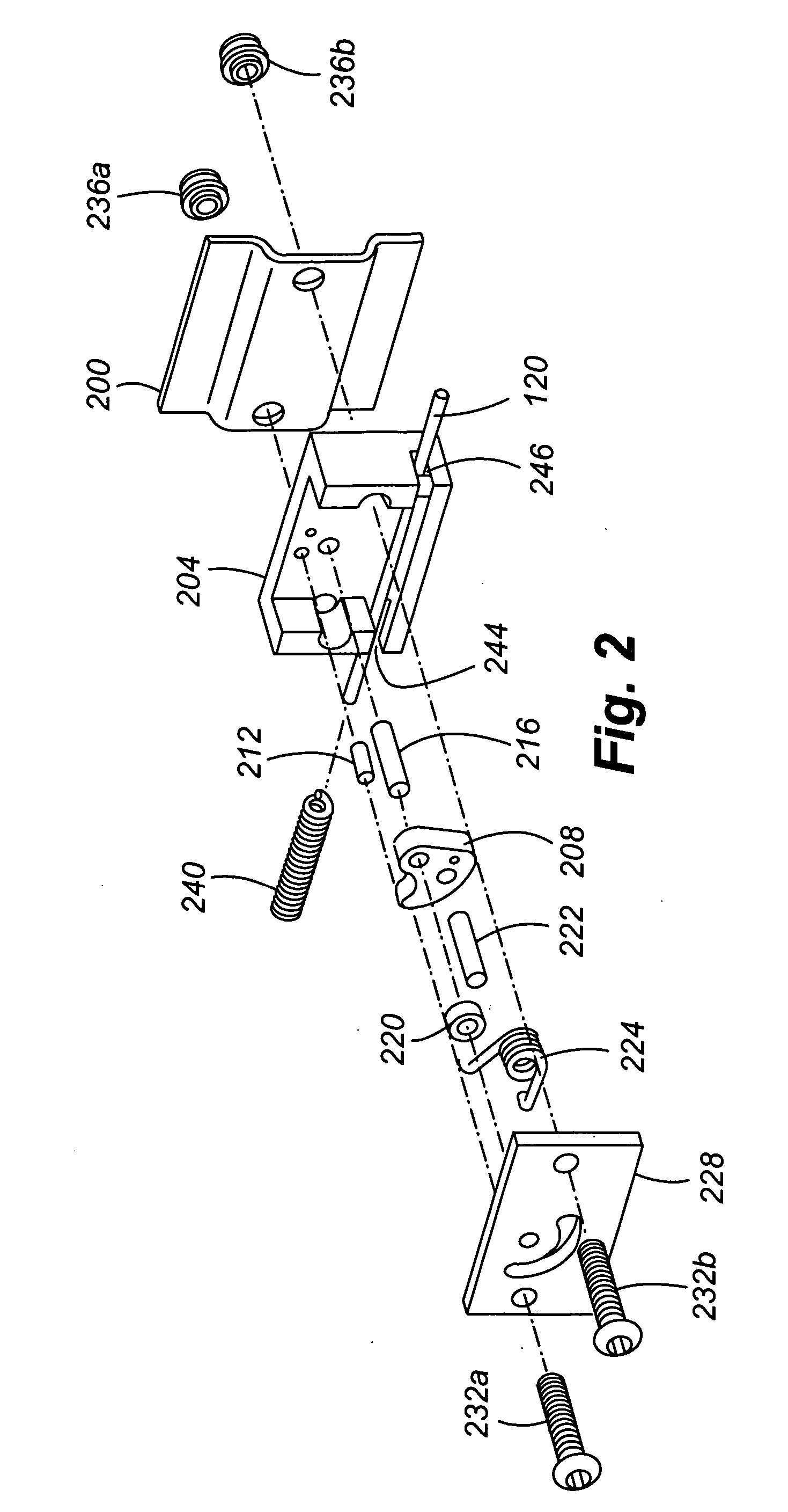
[0038] cable lock device 124 will be discussed with reference to FIGS. 2-5. The cable lock device 124 includes a mounting plate 200, a body 204 engaging the Bowden cable 120, a friction shoe 208 for locking the Bowden cable 120 in a desired position, a movement limiter 212 to limit rotational movement of the shoe, a kingpin 216 about which the shoe rotates, a restraining member 220 to engage the kingpin 216 and hold the shoe in position on the kingpin 216, an actuation lever 222 to permit the user to lock and unlock the shoe against and from, respectively, the cable 120, an over-the-center toggle spring member 224 to bias the shoe against the cable 120, a cover plate 228, and fastening screws 232a,b that engage nuts 236a-b and hold the cover plate 228 on the body 204. The spring member 240 engages the cable inlet cable guide 244 of the body 204. The body 204 further includes a cable outlet guide 246.

[0039]FIG. 3 shows the shoe 208 in a locked position against the cable 120. As can b...

second embodiment

[0047] A hybrid or electromechanical cable lock device of the second embodiment will now be discussed with reference to FIGS. 6-9. As shown in FIGS. 6 and 7, the cable lock device 600 includes a toggle arm lever 604 and shoe 608 pivotably or rotatably mounted about the kingpin 612, the over-the-center spring member 224, the movement limiter 212, the body 616 having an inlet cable guide 620 and outlet guide 624 for the cable 120, and first and second biasing coils, or electromagnets, 628 and 632 for displacing the toggle arm lever 604 between first and second (bi-stable) positions 800 and 804 (FIG. 8). The toggle arm lever 604 includes a magnetic member 700 (FIG. 7) passing through the toggle arm lever 604, such that oppositely polarized faces of the magnet are exposed on each of the first and second sides 704 and 708 of the lever 604. In the absence of the spring member 224, the lever 604 and shoe 608 are rotate independently about the kingpin 612. The spring member 224, however, bi...


PUM


Abstract

A cable lock device includes a body 204, 616 and a frictional shoe 208, 608 operable to engage a Bowden cable 120, wherein, in a first mode, the Bowden cable 120 moves freely in first and second opposing directions 304, 308 and, in a second mode, the shoe inhibits the Bowden cable from moving in the first direction 304 while allowing the Bowden cable to move freely in the second direction 308.

Description

CROSS REFERENCE TO RELATED APPLICATION [0001] The present application claims the benefits of U.S. Provisional Application Ser. No. 60 / 691,377, filed Jun. 17, 2005, entitled “Electromechanical Cable Lock for Prosthetic and Orthotic Devices”, which is incorporated herein by this reference.FIELD OF THE INVENTION [0002] The invention relates generally to prosthetic and orthotic devices and particularly to cable locks for such devices. BACKGROUND OF THE INVENTION [0003] Prosthetic devices, particularly for upper extremity prosthetics, typically include a Bowden cable to control a terminal device to enable the user to grip and release objects. Prosthetic devices are generally of two types, namely voluntary opening and closing devices. In voluntary opening (VO) devices, the terminal device is normally closed. To open the device, the user uses scapular abduction, elbow flexing, or other gross body movements to apply cable tension to the Bowden cable, thereby opening the terminal device. By ...

Claims


Application Information

Patent Timeline
IPC IPC(8): A61F2/54
CPCA61F2/54A61F2/583A61F2/588A61F2/78A61F2002/7862A61F2002/5093A61F2002/6854A61F2002/6863A61F2002/701A61F5/01
Inventor VEATCH, BRADLEY DELTON
Owner ADA TECH
Why Eureka
Try Eureka