
Cryogenic apparatus for chilling beverages and food products and process of manufacturing the same

a technology of beverage container and cryogenic apparatus, which is applied in the field of self-cooling beverage container apparatus, can solve the problems of not meeting the needs of the beverage industry, prior art fails to address the real problems of manufacturing and beverage plant operations, and all prior art designs fail to show how to effectively release high pressure gases without danger

Inactive Publication Date: 2007-02-15
ANTHONY MICHAEL M
View PDF13 Cites 7 Cited by
  • Summary
  • Abstract
  • Description
  • Claims
  • Application Information

AI Technical Summary

Benefits of technology

[0016] An actuation cap protruding stud member protrudes from the inner bottom surface of the actuation cap member. A protruding actuation pin projects centrally from the actuation stud member to form an actuation pin. The top concentric surface of the actuation cap protruding stud member, acts as an actuation cap seal seat for the outer rubber seal member. Before assembling the actuation cap with the assembled receptacle unit, the outer rubber seal is placed by piercing it through the actuation pin and seating said outer rubber seal on the actuation cap seal seat. In case an o-ring is used, no piercing is needed, since the actuation pin can easily passed over the o-ring hole.
[0021] The original bottle is preferably made from a suitable plastic material such as Polyethylene-Teraphthalate, (PET) that can be injection-stretch-blown, so that it is a heat shrinkable material. However, it could also be injection molded and put together using a shrink sleeve band. Thus, the assembly can handle a tremendous amount of pressure stresses.
[0032] It is a further objective of this disclosure to reveal a method of assembling a high pressure cryogenic receptacle into a plastic beverage bottle with a conventional neck finish and into a metal can with a conventional lid without the need for expensive threaded parts.

Problems solved by technology

These earlier inventions do not satisfy all the needs of the beverage industry and they do not use cryogenic refrigerants.
Prior art fails to address the real issues of manufacturing and beverage plant operations that are crucial for the success of a self-cooling beverage container program.
All prior art designs fail to show how to incorporate high pressure gases and effectively release them without danger.
The problem stems from the extreme high pressure of the suitable cryogenic gases such as carbon dioxide or CO2.
No prior art teaches how to manufacture a self-cooling beverage plastic bottle as a simple integrated and manufacturable unit that will conform to the standards of the beverage industry.
Since such receptacles are generally made from thick-walled metallic materials for containing high pressure, rapid heat transfer is limited and almost impossible.
Even with prior designs of co-seamed internal receptacles such as that described in U.S. Pat. No. 6,065,300 to the present inventor the problem was still not solved.
For example, prior art designs do not address easy insertion, self-aligning of the receptacle with the container and so on, particularly when the container is a plastic bottle.
Further, most prior art relies on a separate un-integrated manufacturing process for the attachment of the receptacle to the container.
Most use complicated gaskets and expensive attachment means.
The reason for the improvement is that no other technology addresses the high pressure container costs associated with the manufacture of metal containers.

Method used


Image

  • Cryogenic apparatus for chilling beverages and food products and process of manufacturing the same
  • Cryogenic apparatus for chilling beverages and food products and process of manufacturing the same
  • Cryogenic apparatus for chilling beverages and food products and process of manufacturing the same

Examples


Embodiment Construction

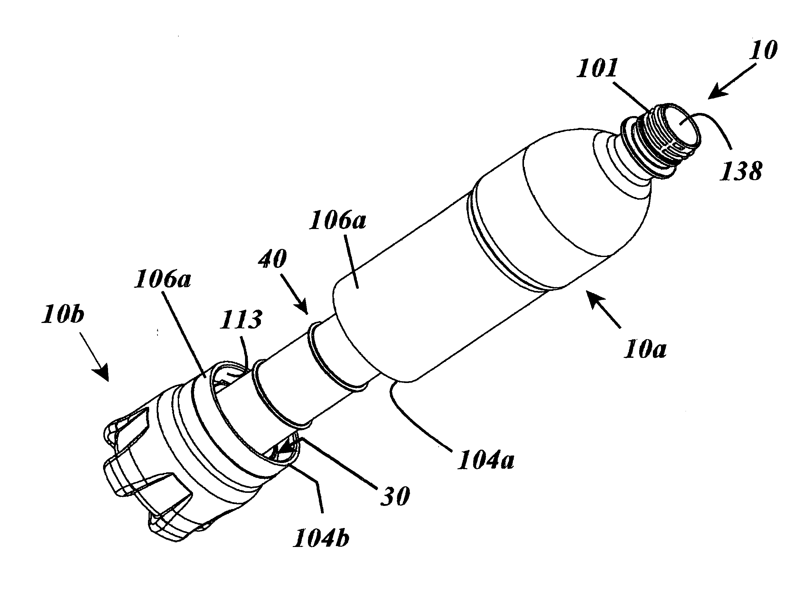
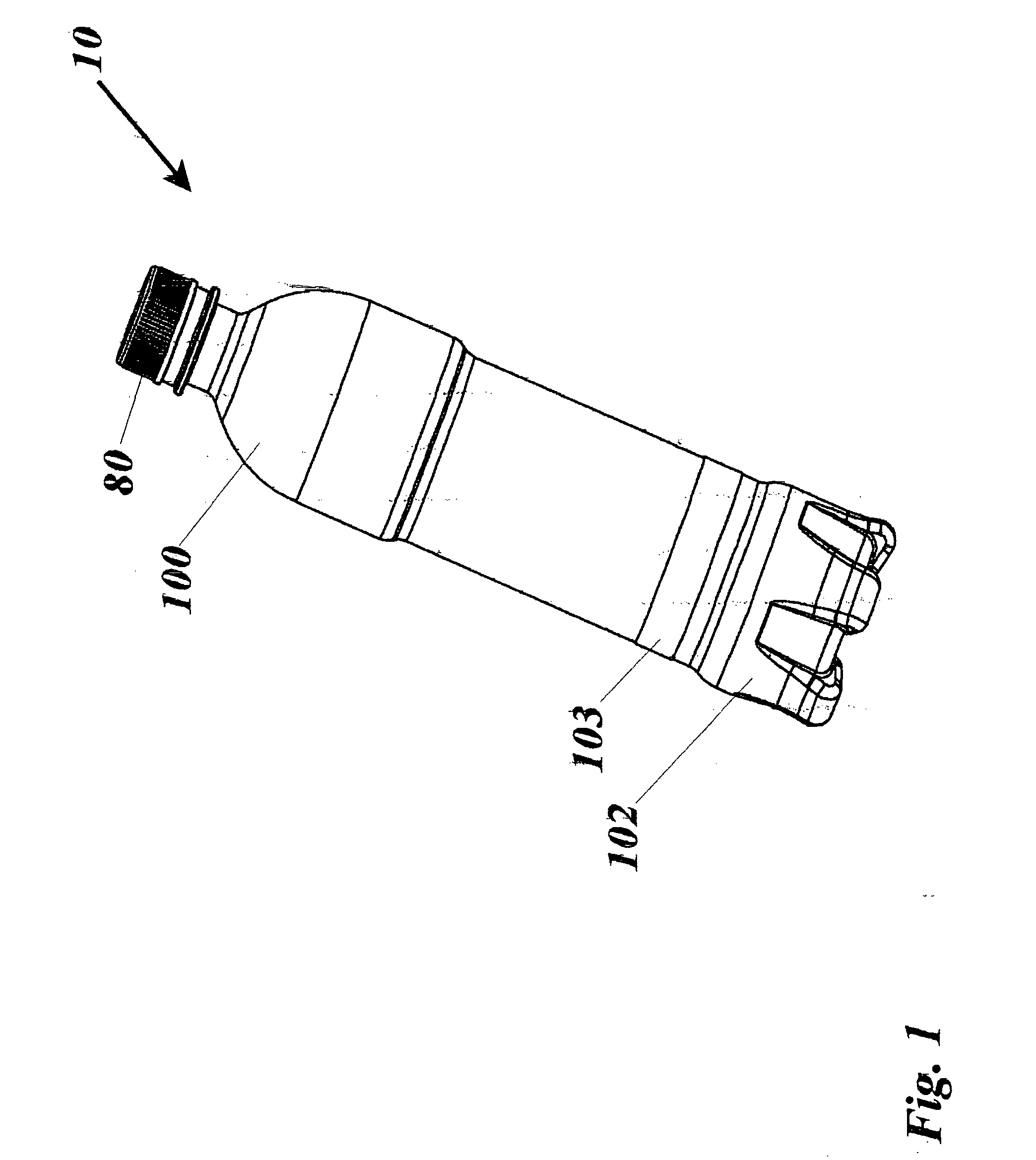
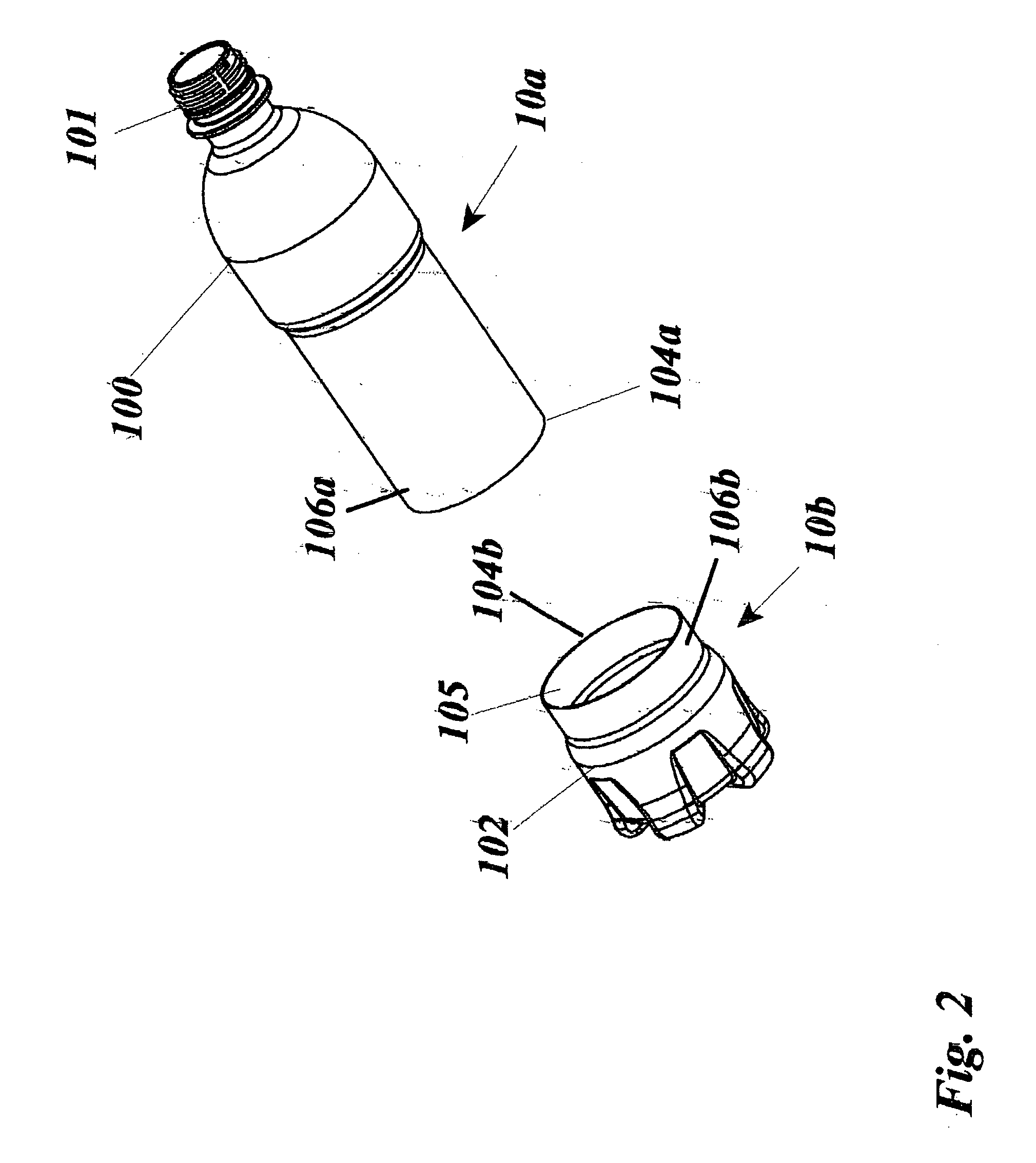
[0065] Referring to FIGS. 1-30, for the preferred of several possible embodiments, the apparatus 10 is a conventional beverage or food container such as a plastic bottle 100 or metal container 143 for containing product 141 to be consumed. In the first embodiment, the bottle container is an injection-stretch-blown plastic bottle 100 with a conventional unified bottom dome 110 and a cylindrical side wall 155 terminating in an open bottle threaded neck 101. The bottle 100 is cut into two separate parts a bottle top member 10a and a bottle bottom member 10b, that can then be thermally sealed together using the refrigerant receptacle assembly 60 of the present invention. The bottle 100 is laser or knife cut into a bottle top member 10a and a bottle bottom member 10b. Alternately, either part can be injection molded from a suitable plastic material, so long as one of the bottle parts is made from a suitable heat shrinkable material. If the bottle top member 10a, and the bottle bottom mem...


PUM


Abstract

Self-cooling food and beverage containers and processes for manufacturing such container0s with cryogenic high-pressure refrigerant cooling apparatus are disclosed. A self-cooling beverage container apparatus containing a beverage or other food product, a method of storing cryogenic gases which then cool said food products, and to methods of assembling and operating the apparatus. A self-cooling beverage container includes a container body having an openable portion, a pressure vessel substantially housed within said container body, the pressure vessel having a first chamber for containing a refrigerant and a charging port, an actuation valve system is configurable from a closed configuration wherein the refrigerant is maintained within the pressure vessel to an open configuration wherein said refrigerant is allowed to expand and exit the pressure vessel upon opening of said container whereby refrigerant expansion and flow through said outlet conduit cools the contents of said container.

Description

CROSS REFERENCE TO RELATED APPLICATIONS [0001] N / A STATEMENT REGARDING FEDERALLY SPONSORED RESEARCH OR DEVELOPMENT [0002] N / A COPYRIGHT NOTICE [0003] A portion of the disclosure of this patent document contains material that is subject to copyright protection. The copyright owner has no objection to the facsimile reproduction by anyone of the patent document or patent disclosure as it appears in the Patent and Trademark Office patent file or records, but otherwise reserves all copyrights rights whatsoever. BACKGROUND OF THE INVENTION [0004] 1. Field of the Invention [0005] The present novel invention relates generally to the field of food and beverage containers and to processes for manufacturing such containers with cryogenic high pressure refrigerant cooling apparatus. More specifically the present invention relates to a self-cooling beverage container apparatus containing a beverage or other food product, a method of storing cryogenic gases which then cool said food products, and...

Claims


Application Information

Patent Timeline
Patent Type & Authority Applications(United States)
IPC IPC(8): B65B63/08F25D3/10F25D3/08
CPCF25D3/107F25D3/14F25D2331/805F25D2331/803F25D31/007
Inventor ANTHONY, MICHAEL M.
Owner ANTHONY MICHAEL M
Learn More