
Flexible bushing assembly for spring brake push rod center seal

a spring brake and center seal technology, applied in the direction of spring/damper, shock absorber, mechanical apparatus, etc., can solve the problems of inability of the braking system to function properly, and achieve the effect of improving the ability of the spring brake push rod center seal, preventing undesirable wear, and maintaining the sealing ability

Inactive Publication Date: 2007-02-15
BENDIKS SPAJSER FAUNDEJSHN BREJK LLK
View PDF17 Cites 24 Cited by
  • Summary
  • Abstract
  • Description
  • Claims
  • Application Information

AI Technical Summary

Benefits of technology

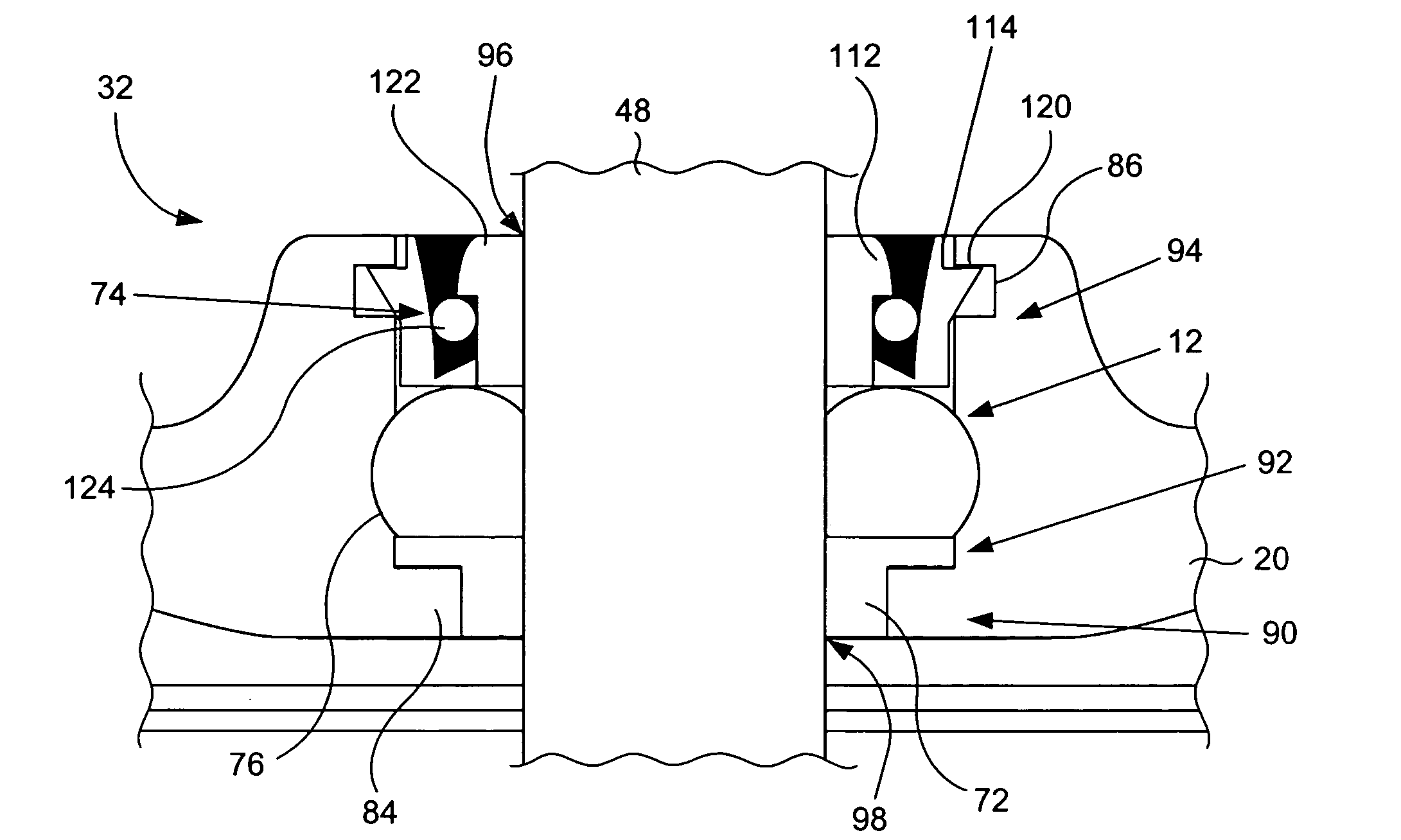
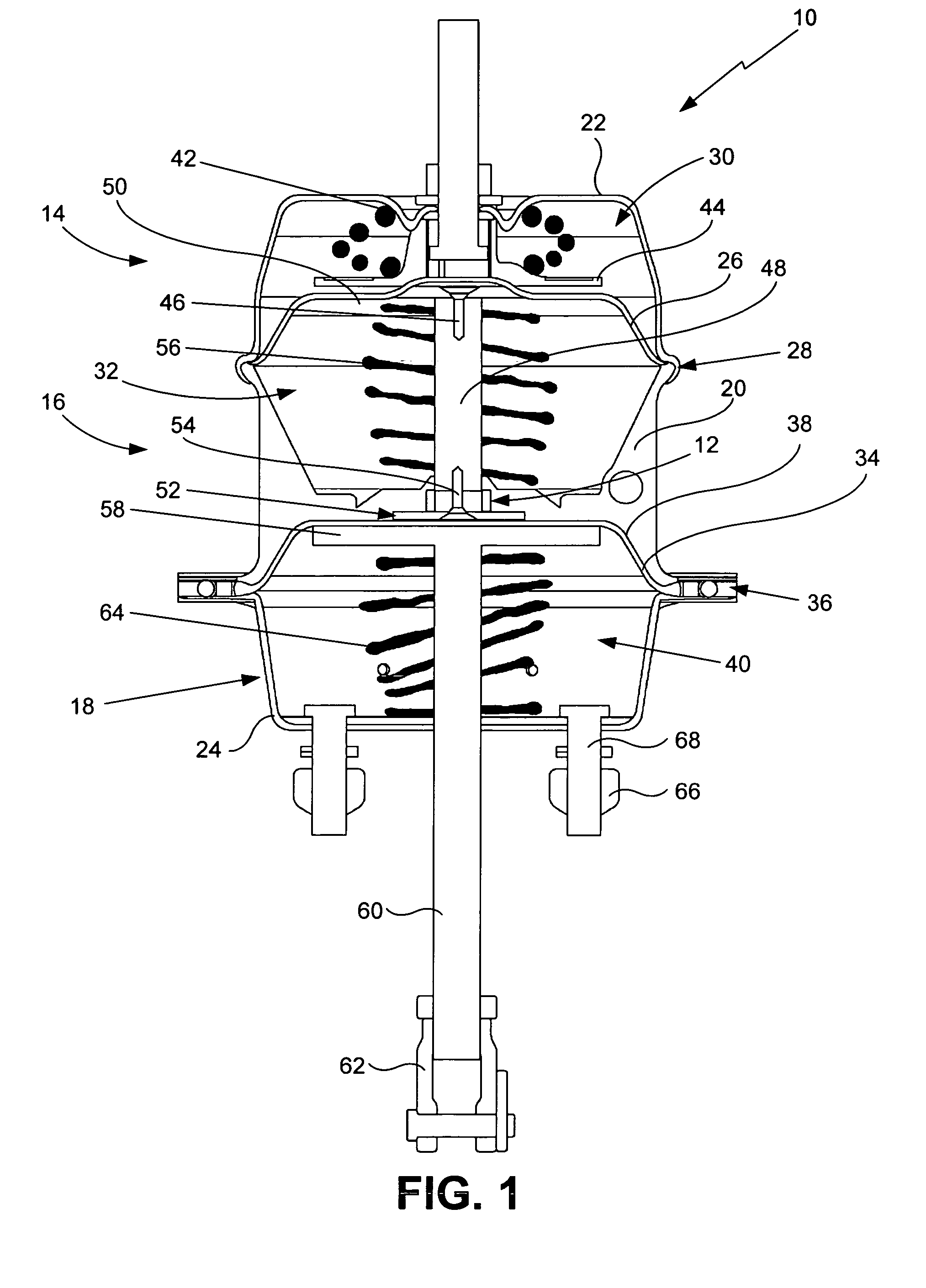
[0011] The flexible bushing assembly for spring brake push rod center seal of the present invention provides the benefits and solves the problems identified above. That is to say, the present invention discloses a bushing assembly that substantially improves the ability of a spring brake push rod center seal to maintain its sealing ability with non-linear and flexing movement of the push rod through the aperture of the adapter base separating a pressurized chamber, such as a parking brake chamber, from a non-pressurized chamber, such as the upper service chamber, of a spring brake actuator. The flexible bushing assembly overcomes the limitations and drawbacks of existing center seal components for spring brake push actuators used in spring brake systems by allowing for the non-linear or flexing movement that is typical of a push rod as it moves through the adapter base aperture in response to the release of pressure from or the application of pressure to the pressurized parking brake chamber. Specifically, the flexible bushing assembly of the present invention comprises a bushing member having a non-continuous width that sealably allows for flexible movement of the push rod through the adapter base commonly utilized in spring brake actuator systems. As such, the flexible bushing assembly of the present invention will substantially eliminate metal to metal contact between the push rod and the adapter base and, as a result prevent the undesirable wear that leads to leaks and brake system failures. The present flexible bushing assembly allows the push rod to pivot in the center seal and find the path therethrough that is best for it to take in light of the off-center movement of the main compression spring, which will substantially reduce the effect of the side forces that are known to cause wear on the center seal and, therefore, increase the life of the center seal. As such, the flexible bushing assembly of the present invention will reduce the maintenance costs for vehicles having spring brake systems and increase the amount of time the vehicle is available for use on the road, where it can be an economic advantage for the owner / operator of the vehicle.
[0013] Accordingly, it is a primary objective of the present invention to provide a flexible bushing assembly for push rod center seals used in spring brake actuators that provides the advantages discussed above and that overcomes the disadvantages and limitations associated with presently configured center seals.
[0014] It is also a primary objective of the present invention to provide a flexible bushing assembly for spring brake push rod center seals that effectively seals the push rod as it moves through the center seal of an adapter base separating a pressurized chamber from a non-pressurized chamber while allowing for non-linear or flexing movement of the push rod to reduce or eliminate the likelihood of excessive wear on the center seal component that can result in leaks and loss of braking system effectiveness.

Problems solved by technology

The improved bushing assembly and spring brake actuator of the present invention reduces the likelihood that non-linear or flexing movement of the push rod will damage the bushing sealing member or the aperture, resulting in the inability of the braking system to function properly.

Method used


Image

  • Flexible bushing assembly for spring brake push rod center seal
  • Flexible bushing assembly for spring brake push rod center seal
  • Flexible bushing assembly for spring brake push rod center seal

Examples


Embodiment Construction

[0033] With reference to the figures where like elements have been given like numerical designations to facilitate the reader's understanding of the present invention, and particularly with reference to the embodiments of the flexible bushing assembly for the spring brake push rod center seal of the present invention illustrated in the figures, various preferred embodiments of the present invention are set forth below. The enclosed description and drawings are merely illustrative of preferred embodiments and represent several different ways of configuring the present invention. Although specific components, materials, configurations and uses of the present invention are illustrated and set forth in this disclosure, it should be understood that a number of variations to the components and to the configuration of those components described herein and in the accompanying figures can be made without changing the scope and function of the invention set forth herein. For purposes of this ...


PUM


Abstract

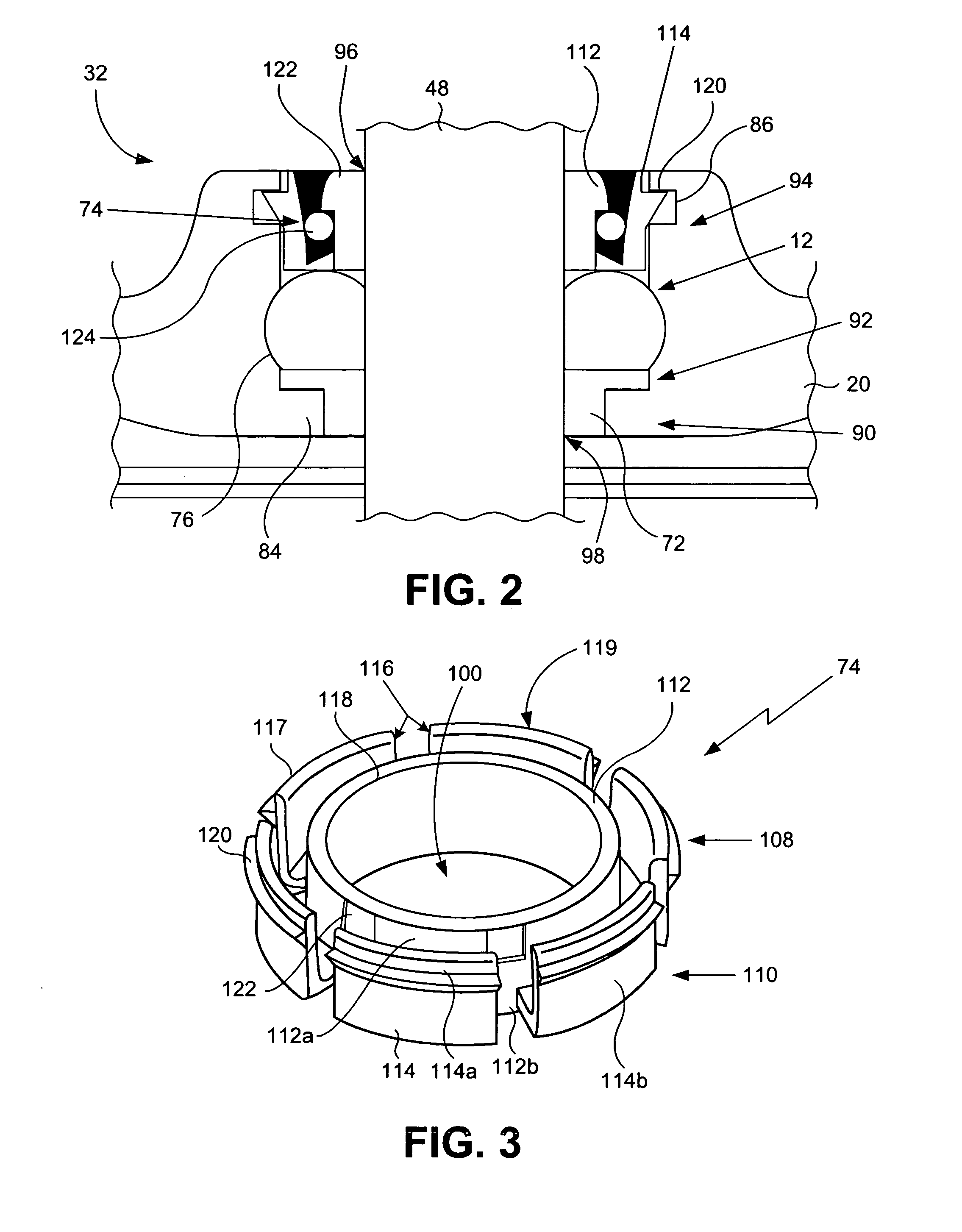
An improved bushing assembly for the center seal used with an adapter base separating pressure chambers in a spring brake actuator to allow a push rod to pass through an aperture therein without loss of pressurized fluid between the pressure chambers. The improved bushing assembly has a flexing component that allows for non-linear or flexing motion of the push rod, a sealing component for sealably engaging the push rod and a locking component for securing the bushing assembly inside the aperture. The improved bushing prevents damage to the sealing member and aperture from the non-linear push rod motion. The flexing component comprises a bushing member having an inner wall and outer wall that form a channel therebetween. The outer wall has engagement tabs to lockingly engage a groove in the aperture to secure the bushing assembly therein. A spring brake adapter is provided that utilizes the improved bushing assembly.

Description

CROSS-REFERENCE TO RELATED APPLICATIONS [0001] None. BACKGROUND OF THE INVENTION [0002] A. Field of the Invention [0003] The field of the present invention relates generally to vehicle braking systems that are operated by air or other fluids. More particularly, the present invention relates to spring brake systems that utilize a spring to drive a rod through an aperture in a wall of pressurized chamber to actuate the brakes and apply a braking force. Even more particularly, the present invention relates to such spring brake systems having a sealing assembly that is configured to allow non-linear or flexing movement of the rod through the aperture. [0004] B. Background [0005] Most large commercial vehicles, such as heavy trucks and the like, utilize a hydraulic spring-operated braking system having a brake actuator that comprises a sealed pressure chamber for the compressed air or other hydraulic fluid used in the system and a powerful main compression spring disposed in a non-pressu...

Claims


Application Information

Patent Timeline
Patent Type & Authority Applications(United States)
IPC IPC(8): F16F9/36
CPCF16D65/28F16D2121/02F16F13/002F16D2123/00F16D2121/12
Inventor THOMPSON, LARRYCARLSON, KEVINMESSER, MATTHEW
Owner BENDIKS SPAJSER FAUNDEJSHN BREJK LLK
Learn More