Deck rail umbrella stand

a technology of umbrella stands and rails, applied in the field of umbrella stands, can solve the problems of not necessarily providing a table, little room, and prior art failing to teach a two-point adjustable support of the typ

Inactive Publication Date: 2007-02-15
BATES EDWARD K
View PDF28 Cites 40 Cited by
  • Summary
  • Abstract
  • Description
  • Claims
  • Application Information

AI Technical Summary

Problems solved by technology

However, the prior art fails to teach a two-point adjustable support of the type presented herein.
However, it is often necessary to mount the umbrella on a deck which provides little room and does not necessarily provide a table.
The prior art does not provide a solution to this problem.

Method used


Image

  • Deck rail umbrella stand
  • Deck rail umbrella stand
  • Deck rail umbrella stand

Examples


Embodiment Construction

[0035] The above described drawing figures illustrate the described apparatus and its method of use in at least one of its preferred, best mode embodiment, which is further defined in detail in the following description. Those having ordinary skill in the art may be able to make alterations and modifications what is described herein without departing from its spirit and scope. Therefore, it must be understood that what is illustrated is set forth only for the purposes of example and that it should not be taken as a limitation in the scope of the present apparatus and method of use.

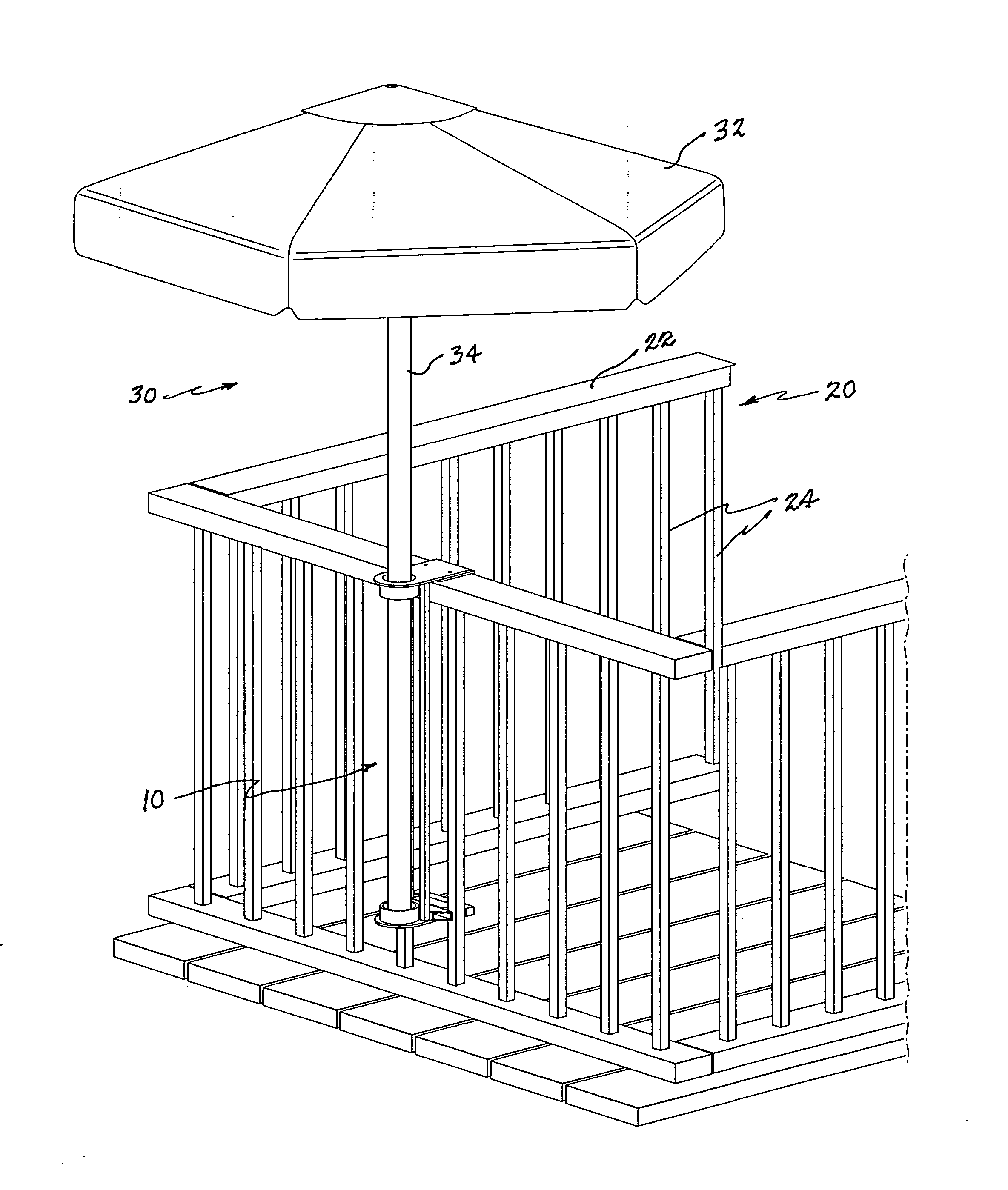
[0036] An umbrella support apparatus 10 is engaged with a fence 20 having a railing 22; typically horizontally disposed, but which may be set at an angle as well, as for on a staircase (not shown). The railing 22 is supported by a plurality of typically vertical, spaced apart, fence posts 24. See FIG. 4. An umbrella 30 has a canopy 32 and a pole 34 for supporting the canopy 32 which is mounted at an upper...


PUM


Abstract

An umbrella support apparatus is designed to engage a fence having a railing which is supported by a plurality of fence posts. A railing jaw receiver is positioned over the fence railing and a post clamp receiver is positioned below the jaw receiver and clamped to the fence posts. A strut is engaged between the jaw receiver and the clamp receiver with the jaw receiver providing a ring adapted for passing an umbrella pole through. The umbrella pole is then engaged with the clamp receiver which provides an umbrella pole terminal end engagement fixture for restraining the umbrella pole vertically and laterally.

Description

BACKGROUND RELATED APPLICATIONS [0001] none [0002] 1. Field of the Present Disclosure [0003] This disclosure relates generally to umbrella stands and more particularly to an umbrella stand that is configured for being mounted onto a deck railing. [0004] 2. Description of Related Art [0005] The following art defines the present state of this field and each disclosure is hereby incorporated herein by reference: [0006] Kizer, U.S. Pat. No. 278,973, discloses an adjustable umbrella-support, the crank rod, spring catch, and ears or disks, in combination with the notched disk, pivoted between the disks, and provided with the socket. [0007] Hohl, U.S. Pat. No. 1,162,608, discloses an umbrella supporting device, the combination with a socket through which the stem of the umbrella is adapted to extend the socket having a plurality of spaced projecting portions, of means for securing the stem of the umbrella in the socket, a horizontal bar connecting with the socket, means for securing the so...

Claims


Application Information

Patent Timeline
Patent Type & Authority Applications(United States)
IPC IPC(8): F21V21/00
CPCE04H12/2276A45B23/00
Inventor BATES, EDWARD K.
Owner BATES EDWARD K
Why Eureka
Try Eureka