Methods and systems for automated pipeline testing

a pipeline and automated technology, applied in the field of underground pipeline maintenance and testing, can solve the problems of high manual process of conducting close interval surveys, potential errors, and inherently subject to corrosion of pipes and other metallic structures

Inactive Publication Date: 2007-02-15
ELECSYS INT CORP
View PDF14 Cites 34 Cited by
  • Summary
  • Abstract
  • Description
  • Claims
  • Application Information

AI Technical Summary

Benefits of technology

[0012] There is an increasing interest in checking the polarized voltage (or instant off potential) at pipe-to-soil test points as well as the constant potential at these sites. The polarized voltage tests supply pertinent pi

Problems solved by technology

Pipelines and other metallic structures inherently are subject to corrosion when placed underground.
However, conducting close interval surveys is a highly manual process, with a potential for errors, as described below.
If the team cannot verify that the cycling activity was properly conducted at each rectifier location, the resulting collected data is rendered questionable and the survey may have to be repeated.
Underground pipelines may be adjacent to or near o

Method used


Image

  • Methods and systems for automated pipeline testing
  • Methods and systems for automated pipeline testing
  • Methods and systems for automated pipeline testing

Examples


Embodiment Construction

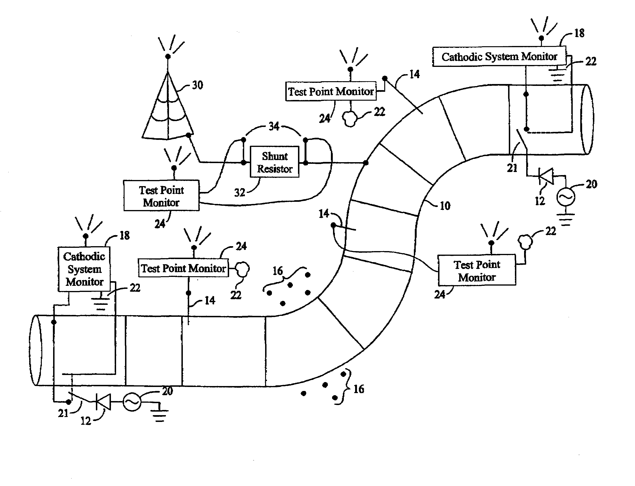
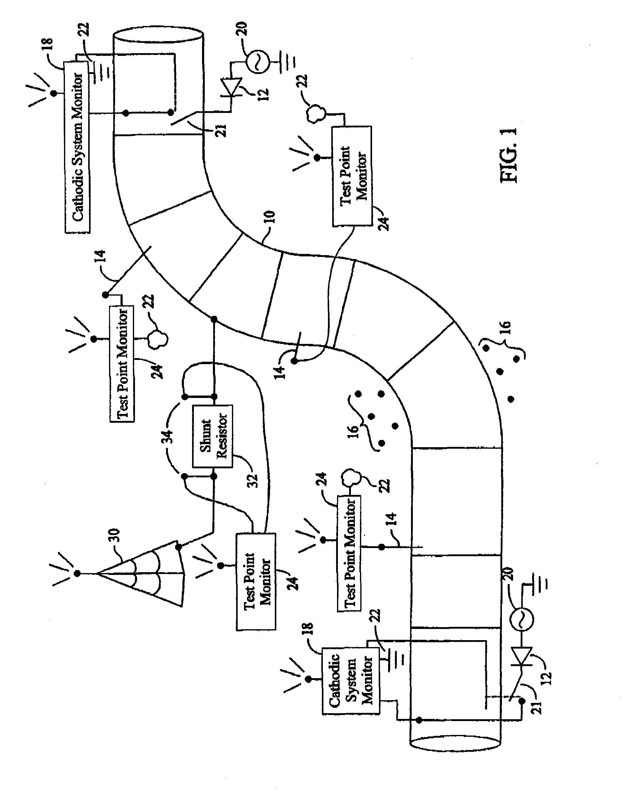
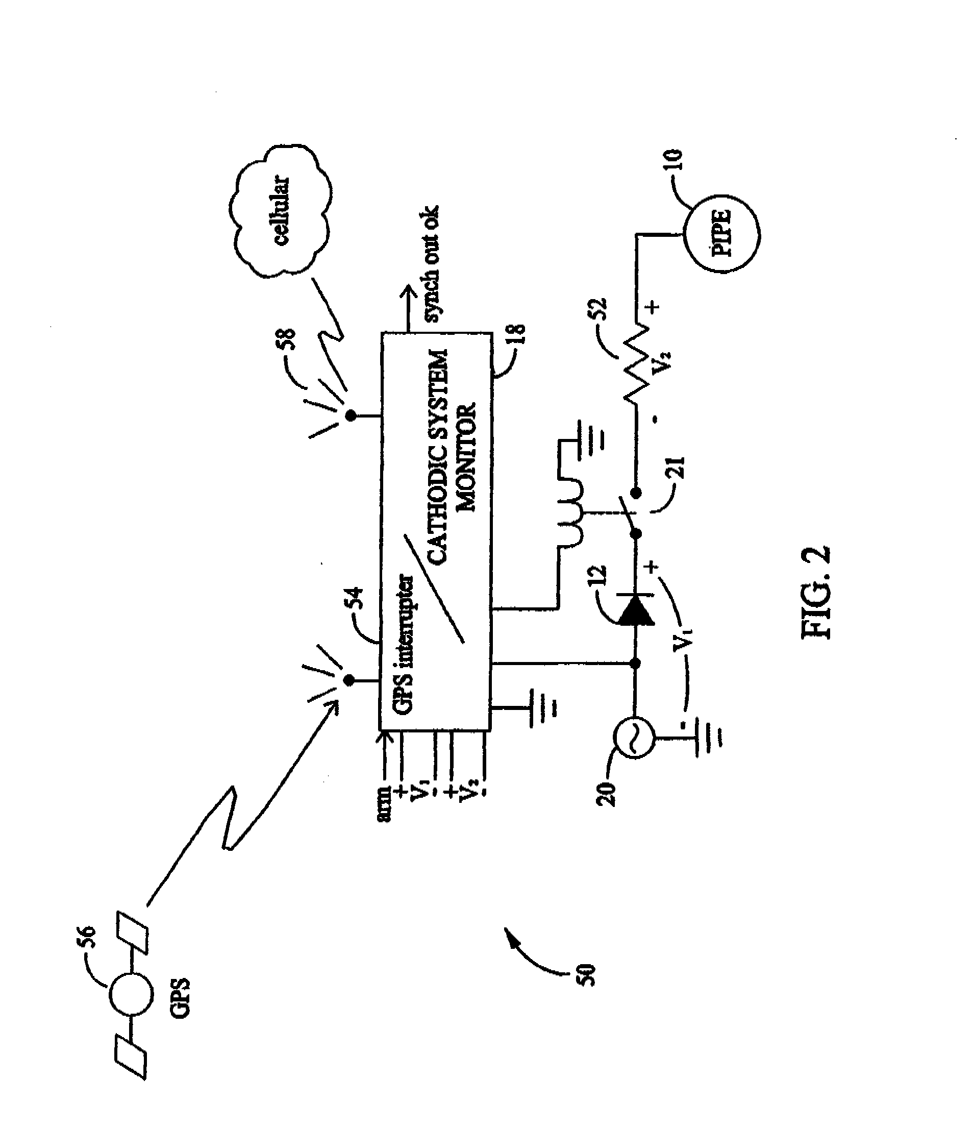
[0032]FIG. 1 is a schematic diagram of a pipeline 10 illustrating cathodic protection rectifiers 12, test points 14, and close interval survey test points 16. Cathodic system monitors 18 are utilized to measure, verify, and report output voltages and applied currents from cathodic protection rectifiers 12 on a pre-determined schedule, for example, once every two months. Cathodic system monitors 18 (described further in FIG. 2) are utilized to measure applied current, in one embodiment, by measuring a voltage drop across a low resistance value resistor (e.g. a shunt resistor (shown in FIG. 2)). Monitors 18 may also be configured to monitor power 20. In a particular embodiment, monitors 18 are configured to control switching devices, for example, relays 21 which switch the voltage output from cathodic protection rectifiers 12 to pipeline 10.

[0033] Known cathodic protection rectifiers are typically placed along a pipeline, for example, every three to five miles. The rectifiers are uti...


PUM


Abstract

A method for testing effectiveness of a cathodic protection device configured to apply at least one voltage across an underground structure and a reference point is described. The method includes providing a sample of the material from which the underground structure is fabricated, placing the sample proximate the underground structure, electrically connecting the sample to the underground structure through a switch, operating the switch at predetermined intervals, and measuring electrical characteristics of the sample at intervals based at least partially on the predetermined intervals and a position of the switch

Description

CROSS REFERENCE TO RELATED APPLICATIONS [0001] This application is a continuation-in-part application of U.S. patent application Ser. No. 10 / 873,473, filed Jun. 22, 2004, which is a continuation-in-part application of U.S. patent application Ser. No. 10 / 096,200, filed Mar. 12, 2002, issued as U.S. Pat. No. 6,822,432 on Nov. 23, 2004, which claims the benefit of U.S. Provisional Application No. 60 / 300,348, filed Jun. 22, 2001, all of which are hereby incorporated by reference in their entirety.BACKGROUND OF THE INVENTION [0002] This invention relates generally to underground pipelines, and more specifically to maintenance and testing of underground pipelines. [0003] Pipelines and other metallic structures inherently are subject to corrosion when placed underground. The corrosion process involves the removal of electrons or oxidation of the metal, and consumption of those electrons by some other reduction reaction, such as oxygen or water reduction. Corrosion is encouraged by the pres...

Claims


Application Information

Patent Timeline
IPC IPC(8): G01R27/08
CPCG01N17/02C23F13/22
Inventor HILLEARY, THOMAS N.
Owner ELECSYS INT CORP
Why Eureka
Try Eureka