
Organic light emitting display device

a technology of light-emitting display and organic materials, which is applied in the direction of lighting apparatus, instruments, light sources, etc., can solve the problems of insufficient bonding of conventional oled devices, production equipment affected by panel size, and difficulty in increasing the panel's siz

Active Publication Date: 2007-02-15
SAMSUNG DISPLAY CO LTD
View PDF5 Cites 35 Cited by
  • Summary
  • Abstract
  • Description
  • Claims
  • Application Information

AI Technical Summary

Benefits of technology

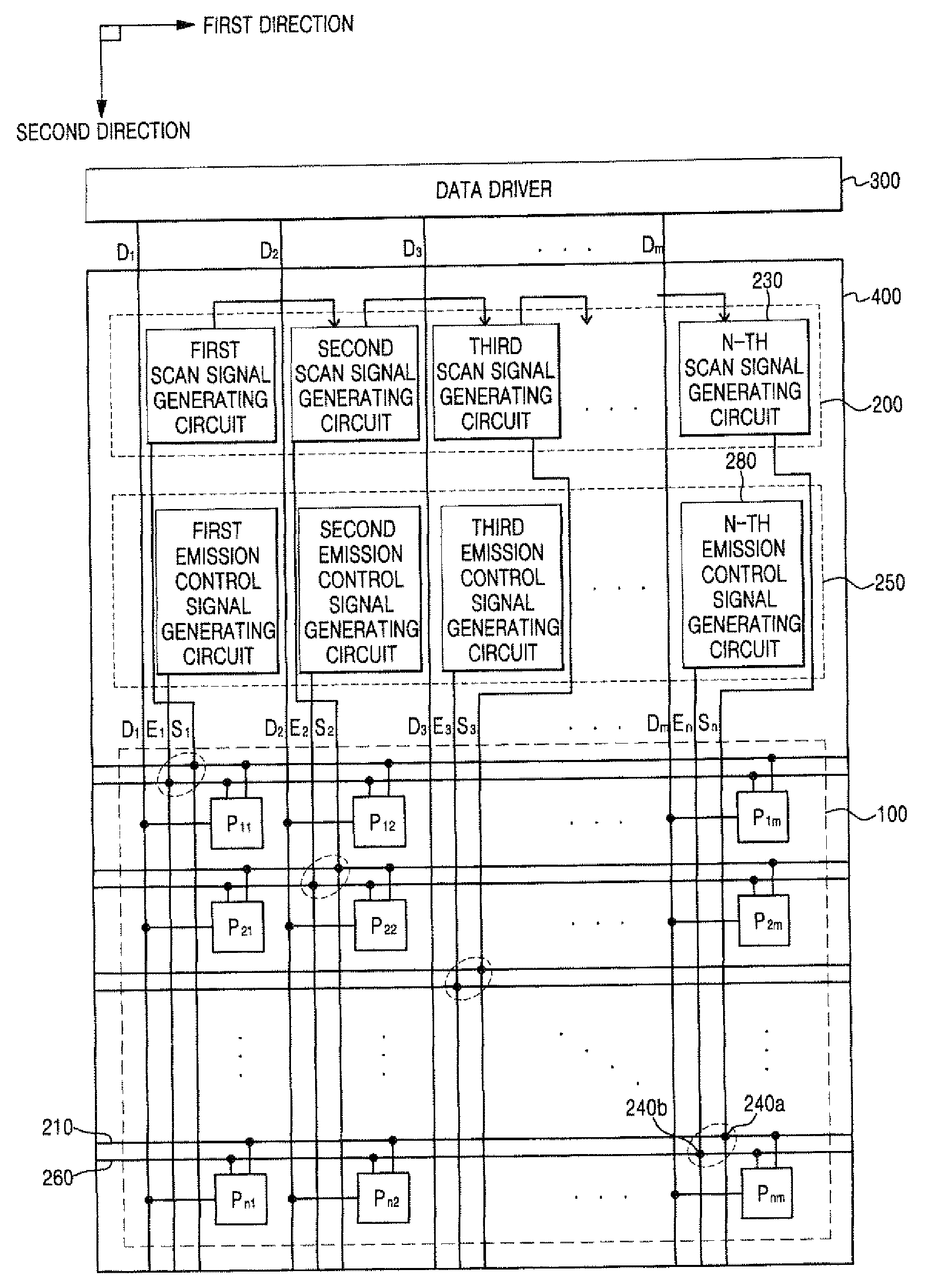
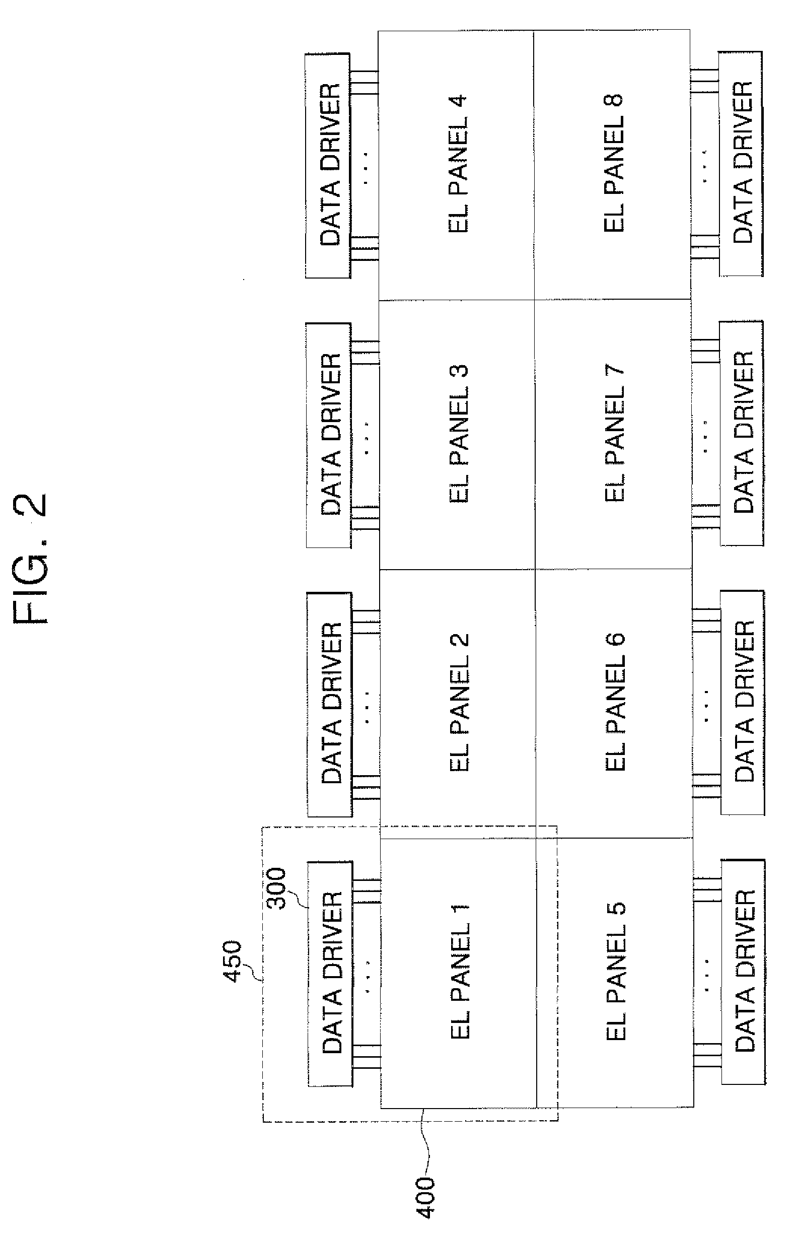
[0017] The present invention provides an organic light emitting display (OLED) device in which data, scan, and emission control drivers are arranged so that multiple electroluminescent (EL) panels may be more easily bonded together.

Problems solved by technology

In such an OLED device, it is difficult to increase the panel's size because an IR drop occurs depending on the length of a line to which a power supply voltage is applied, and production equipment is affected by the panel's size.
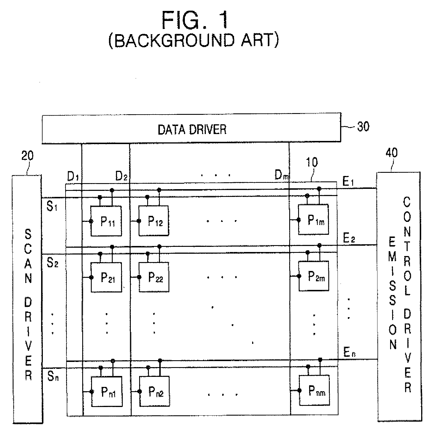
However, the conventional OLED device may be inadequate to the bonding of the panels since drivers, such as the data driver 30, the scan driver 20, and the emission control driver 40, are typically formed at multiple sides of the pixel portion 10.
Also, the OLED device may have non-uniform luminance at interfaces between bonded panels.

Method used


Image

  • Organic light emitting display device
  • Organic light emitting display device
  • Organic light emitting display device

Examples


Embodiment Construction

[0029] The present invention is described more fully hereinafter with reference to the accompanying drawings, in which exemplary embodiments of the invention are shown. This invention may, however, be embodied in many different forms and should not be construed as limited to the embodiments set forth herein. Rather, these embodiments are provided so that this disclosure is thorough, and will fully convey the scope of the invention to those skilled in the art. In the drawings, the size and relative sizes of layers and regions may be exaggerated for clarity. Like reference numerals in the drawings denote like elements.

[0030] It will be understood that when an element such as a layer, film, region or substrate is referred to as being “on” another element, it can be directly on the other element or intervening elements may also be present. In contrast, when an element is referred to as being “directly on” another element, there are no intervening elements present.

[0031]FIG. 2 shows an...


PUM


Abstract

An organic light emitting display (OLED) device including a plurality of electroluminescent (EL) panels that are coupled with one another. In order to facilitate the coupling of the EL panels, respective data drivers are disposed at one side of pixels, and a scan driver and an emission control driver are formed in each of the EL panels. Thus, surfaces of the EL panels that are not connected to data drivers may be coupled with one another to form the OLED device. In the OLED device, a data driver is not formed at interfaces between the EL panels, and uniform pixels are arranged, so that non-uniformity in luminance may be prevented.

Description

CROSS-REFERENCE TO RELATED APPLICATION [0001] This application claims priority to and the benefit of Korean Patent Application No. 10-2005-0074366, filed Aug. 12, 2005, which is incorporated herein by reference for all purposes as if fully set forth herein. BACKGROUND OF THE INVENTION [0002] 1. Field of the Invention [0003] The present invention relates to an organic light emitting display (OLED) device, and more particularly, to an OLED device in which a plurality of electroluminescent (EL) panels are coupled together. [0004] 2. Discussion of the Background [0005] Flat panel display (FPD) devices are being actively researched. Organic light emitting display (OLED) devices have particularly attracted much attention as next-generation FPDs because of their high luminance and wide viewing angle. [0006] Unlike liquid crystal display (LCD) devices, the OLED devices do not need an additional light source because they utilize self-emissive light emitting diodes. The intensity of light emi...

Claims


Application Information

Patent Timeline
Patent Type & Authority Applications(United States)
IPC IPC(8): G09G3/30
CPCG09G3/3208G09G3/3266G09G2310/0221G09G5/02G09G2300/0426G09G3/3275G09G2310/0278H05B33/26
Inventor YOON, HAN-HEE
Owner SAMSUNG DISPLAY CO LTD
Features
  • Generate Ideas
  • Intellectual Property
  • Life Sciences
  • Materials
  • Tech Scout
  • Unparalleled Data Quality
  • Higher Quality Content
  • 60% Fewer Hallucinations
Learn More