
Double-skin structure and method of manufacturing thereof

Active Publication Date: 2019-09-12
MITSUBISHI HEAVY IND LTD
View PDF0 Cites 1 Cited by
  • Summary
  • Abstract
  • Description
  • Claims
  • Application Information

AI Technical Summary

Benefits of technology

The patent text is about a new invention that improves the aesthetic and reduces distortion when joining parts of a double-skin structure together through welding. By using a bonding portion that joins the cover, first mold member, and second mold member, the amount of distortion is minimized compared to joining the entire structure through welding. This also helps to improve the overall aesthetic appearance of the double-skin structure without adding manufacturing steps.

Problems solved by technology

For this reason, the number of manufacturing steps for the double-skin structure increases, and the manufacturing process becomes complicated.
Because the arc welding causes a large weld deformation, there is the possibility that the aesthetic of the double-skin structure deteriorates.

Method used


Image

  • Double-skin structure and method of manufacturing thereof
  • Double-skin structure and method of manufacturing thereof
  • Double-skin structure and method of manufacturing thereof

Examples


first embodiment

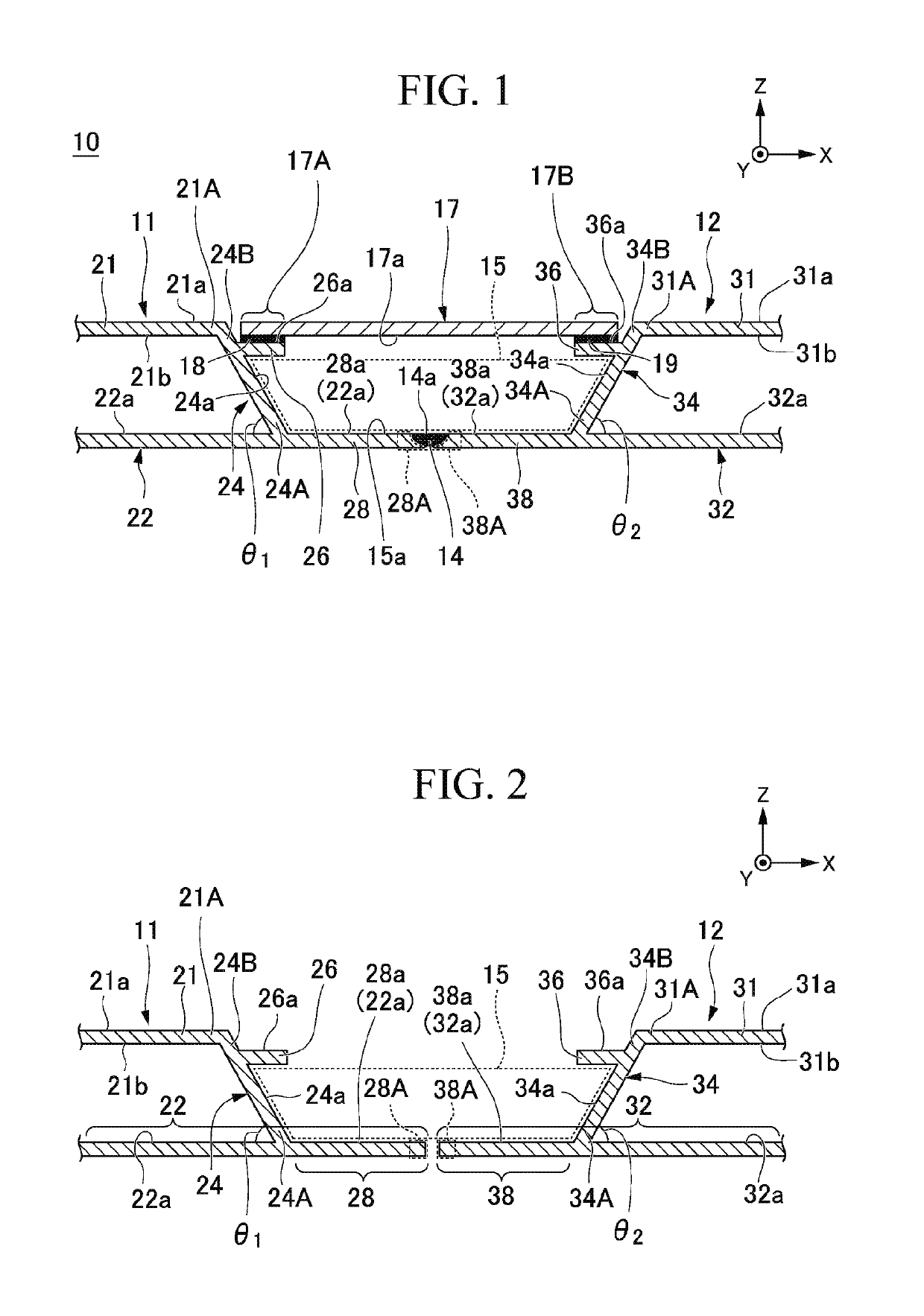
[0087]A double-skin structure 10 of a first embodiment will be described with reference to FIGS. 1 and 2. In FIGS. 1 and 2, an X direction denotes an arrangement direction (in other words, a width direction of a cover plate 17) of a first mold member 11 and a second mold member 12, a Y direction denotes a longitudinal direction of the cover plate 17 which is perpendicular to the X direction, and a Z direction denotes a vertical direction perpendicular to the X direction and the Y direction. FIG. 2 schematically shows a state where the first mold member 11 and the second mold member 12 are not connected together.

[0088]The double-skin structure 10 of the first embodiment has the first mold member 11; the second mold member 12; a connection portion 14; a recessed portion 15; the cover plate 17 which is a cover portion; and bonding portions 18 and 19.

[0089]The first mold member 11 and the second mold member 12 are disposed in the X direction such that the recessed portion 15 is bounded ...

second embodiment

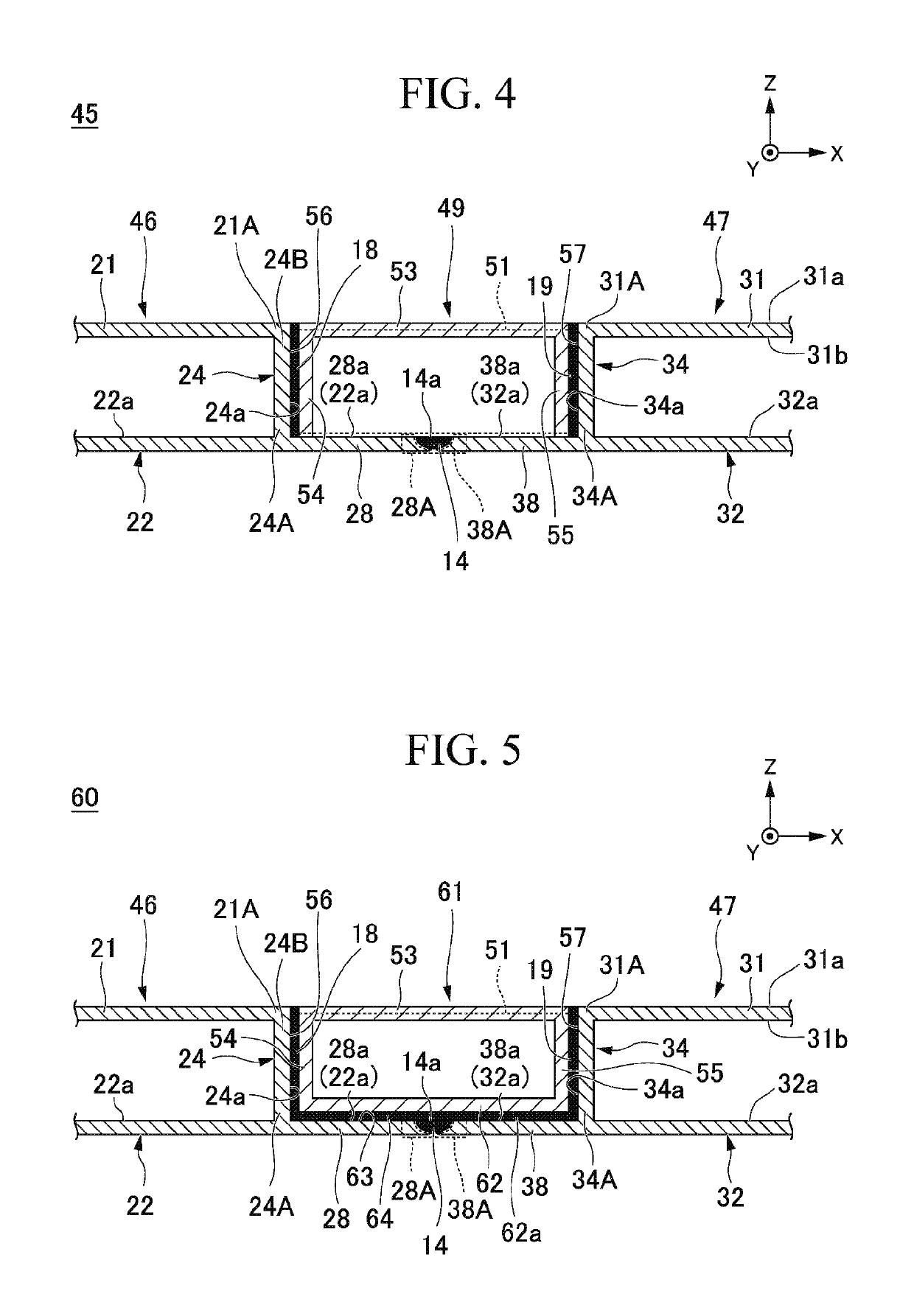
[0153]A double-skin structure 45 of a second embodiment will be described with reference to FIG. 4. In FIG. 4, the same reference symbols will be assigned to the same configuration elements as those of the structure shown in FIGS. 1 and 2.

[0154]The double-skin structure 45 has a first mold member 46; a second mold member 47; the connection portion 14; a recessed portion 51; a cover portion 49; and the bonding portions 18 and 19.

[0155]The first mold member 46 has the same configuration as that of the first mold member 11 except that the first extension portion 26 is removed from the configuration elements of the first mold member 11 described in the first embodiment, and the first rib 24 is disposed perpendicular to the first upper plate 21 and the first lower plate 22.

[0156]The second mold member 47 has the same configuration as that of the second mold member 12 except that the second extension portion 36 is removed from the configuration elements of the second mold member 12 descri...

third embodiment

[0186]A double-skin structure 90 of a third embodiment will be described with reference to FIG. 8. In FIG. 8, the same reference symbols will be assigned to the same configuration elements as those of the structure shown in FIG. 4.

[0187]The double-skin structure 90 of the third embodiment has the same configuration as that of the double-skin structure 45 of the second embodiment except that the double-skin structure 90 has a first mold member 91 and a cover portion 93 instead of the first mold member 46 and the cover portion 49 of the double-skin structure 45.

[0188]The first mold member 91 has the same configuration as that of the first mold member 11 except that the first extension portion 26 is removed from the configuration of the first mold member 11 described in the first embodiment. That is, the first rib 24 of the first mold member 91 is inclined with respect to the upper surface 22a of the first lower plate 22.

[0189]A recessed portion 92 is formed between the first mold memb...


PUM


Abstract

There is provided a double-skin structure in which it is possible to obtain an aesthetic improvement in addition to restricting an increase in the number of manufacturing steps. The structure includes a connection portion connecting together an end portion of a first projection portion of a first mold member and an end portion of a second projection portion of a second mold member; a cover plate that is provided between the first mold member and the second mold member, and that blocks an upper end side of a recessed portion bounded by a first rib, a second rib, the first projection portion, and the second projection portion; and a bonding portion that bonds the cover plate to the first mold member, and the cover plate to the second mold member.

Description

TECHNICAL FIELD OF THE INVENTION[0001]The present invention relates to a double-skin structure and a method of manufacturing thereof. Priority is claimed on Japanese Patent Application No. 2018-044438, filed on Mar. 12, 2018, the content of which is incorporated herein by reference.BACKGROUND ART[0002]In the related art, in the view of realizing a weight reduction and improving pressure resistance in relation to streamlining and speeding up the manufacturing of transport vehicles, a double-skin structure is manufactured as a vehicle frame fabricated from a large hollow mold member made from a light alloy (for example, Japanese Patent No. 3807766). In the double-skin structure, it is necessary to join together two points on exterior and interior sides of a vehicle.[0003]Japanese Patent No. 3807766 discloses arc welding used as a method of joining the double-skin structure.DISCLOSURE OF THE INVENTION[0004]If the joining of the double-skin structure is performed via only arc welding as...

Claims


Application Information

Patent Timeline
IPC IPC(8): B62D25/20B32B7/04B32B3/30B32B15/01B62D25/04B62D27/02
CPCB32B3/30B62D25/20B62D25/04B62D29/008B62D27/02B32B2605/00B32B7/04B32B15/016B62D27/026B62D25/025B62D33/044B62D25/02
Inventor KANNO, TOSHIFUMI
Owner MITSUBISHI HEAVY IND LTD
Features
  • Generate Ideas
  • Intellectual Property
  • Life Sciences
  • Materials
  • Tech Scout
  • Unparalleled Data Quality
  • Higher Quality Content
  • 60% Fewer Hallucinations
Learn More