Projector and method for manufacturing projector
a technology of projectors and manufacturing methods, applied in projectors, color television details, instruments, etc., can solve the problems of difficult to adjust the size of the illumination area, work that requires a lot of time and labor, and traditional projectors
- Summary
- Abstract
- Description
- Claims
- Application Information
AI Technical Summary
Benefits of technology
Problems solved by technology
Method used
Image


Examples
embodiment 1
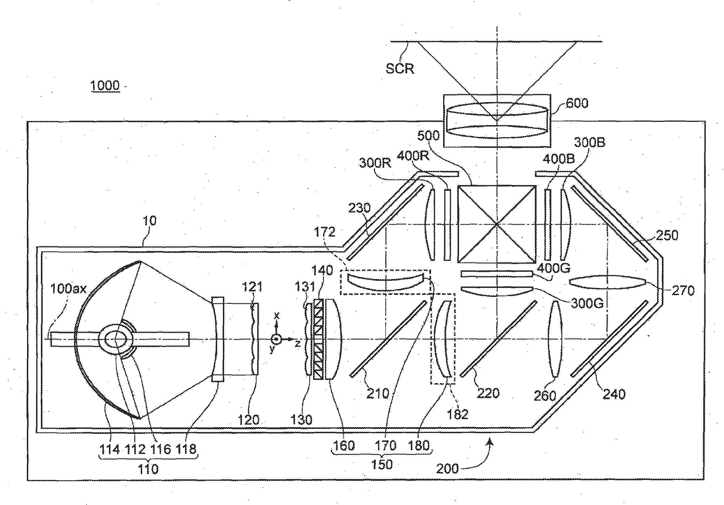
[0075]FIG. 1 shows an optical system of a projector 1000 according to Embodiment 1. In the following description, the three directions orthogonal to each other are referred to as z-axis direction (direction of illumination optical axis 1000ax in FIG. 1), x-axis direction (direction parallel to the paper surface and orthogonal to the z-axis direction in FIG. 1), and y-axis direction (direction perpendicular to the paper surface and orthogonal to the z-axis direction in FIG. 1).
[0076] The projector 1000 according to Embodiment 1 is a projector including: a light source 110 that emits a luminous flux; a first lens array 120 having plural first small lenses 121 that split the luminous flux from the light source 110 into plural partial luminous fluxes; second lens array 130 having plural second small lenses 131 corresponding to the plural first small lenses 121; a polarization conversion element 140 that emits the respective partial luminous fluxes split by the first lens array 120 as s...
embodiment 2
[0144]FIG. 4 shows an optical system of a protector 1002 according to Embodiment 2. In FIG. 4, the same members as in FIG. 1 are denoted by the same numerals and will not be described further in detail.
[0145] The projector 1002 according to Embodiment 2 has basically the same construction as the projector 1000 according to Embodiment 1, but the directions of the first optical lens and the second optical lens and the construction of the first lens array and the second lens array are different from those in the projector 1000 according to Embodiment 1, as shown in FIG. 4.
[0146] In the projector 1002 according to Embodiment 2, the first optical lens 170 and the second optical lens 180 are arranged with their concave surfaces directed toward the light incident side, as shown in FIG. 4. Thus, the focal length f3 of the superimposing system 150 can be reduced while the focal position of the superimposing system 150 is maintained.
[0147] Also, in the projector 1002 according to Embodimen...
embodiment 3
[0150]FIG. 5 shows an optical system of a projector 1004 according to Embodiment 3. In FIG. 5, the same members as in FIG. 1 are denoted by the same numerals and will not be described further in detail.
[0151] The projector 1009 according to Embodiment 3 has basically the same construction as the projector 1000 according to Embodiment 1, but the directions of the first optical lens and the second optical tens and the construction of the first lens array and the second lens array are different from those in the projector 1000 according to Embodiment 1, as shown in FIG. 5.
[0152] In the projector 1004 according to Embodiment 3, the first optical lens 170 and the second optical lens 180 are arranged with their concave surfaces directed toward the light incident side, as shown in FIG. 5. Thus, the focal length f3 of the superimposing system 150 can be reduced while the focal position of the superimposing system 150 is maintained.
[0153] Also, in the projector 1004 according to Embodimen...
PUM
 Abstract
Description
Claims
Application Information
 - R&D
- Intellectual Property
- Life Sciences
- Materials
- Tech Scout
- Unparalleled Data Quality
- Higher Quality Content
- 60% Fewer Hallucinations
Browse by: Latest US Patents, China's latest patents, Technical Efficacy Thesaurus, Application Domain, Technology Topic, Popular Technical Reports.
© 2025 PatSnap. All rights reserved.Legal|Privacy policy|Modern Slavery Act Transparency Statement|Sitemap|About US| Contact US: help@patsnap.com