Image forming apparatus
a technology of forming apparatus and forming chamber, which is applied in the direction of electrographic process apparatus, instruments, optics, etc., can solve the problems of difficult disposal of jams generated in sheet conveying units b>105/b>, difficult access to this region, etc., and achieve the effect of improving ease of maintenan
- Summary
- Abstract
- Description
- Claims
- Application Information
AI Technical Summary
Benefits of technology
Problems solved by technology
Method used
Image

Examples
first exemplary embodiment
[Exemplary Image Forming Apparatus]
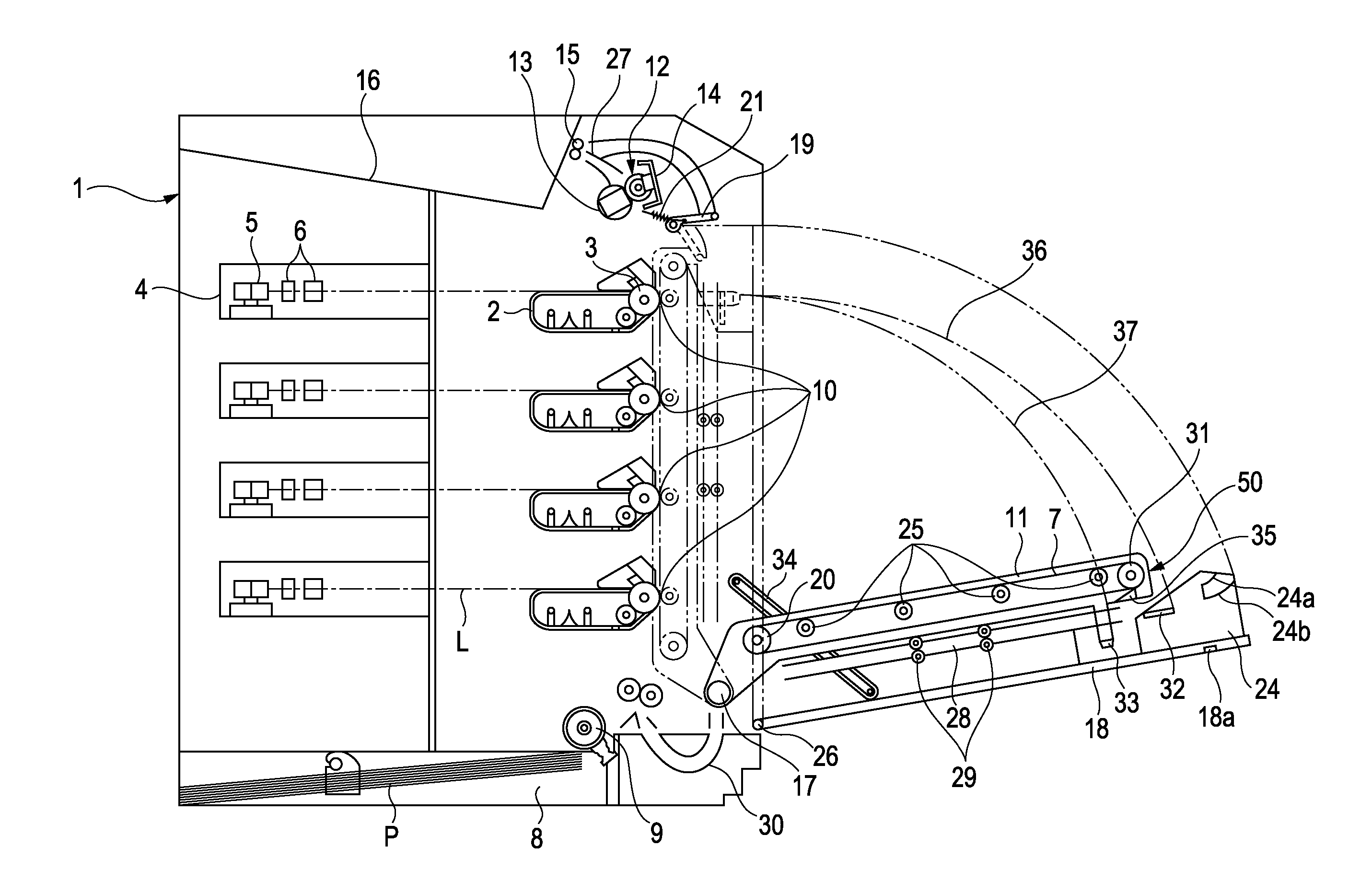
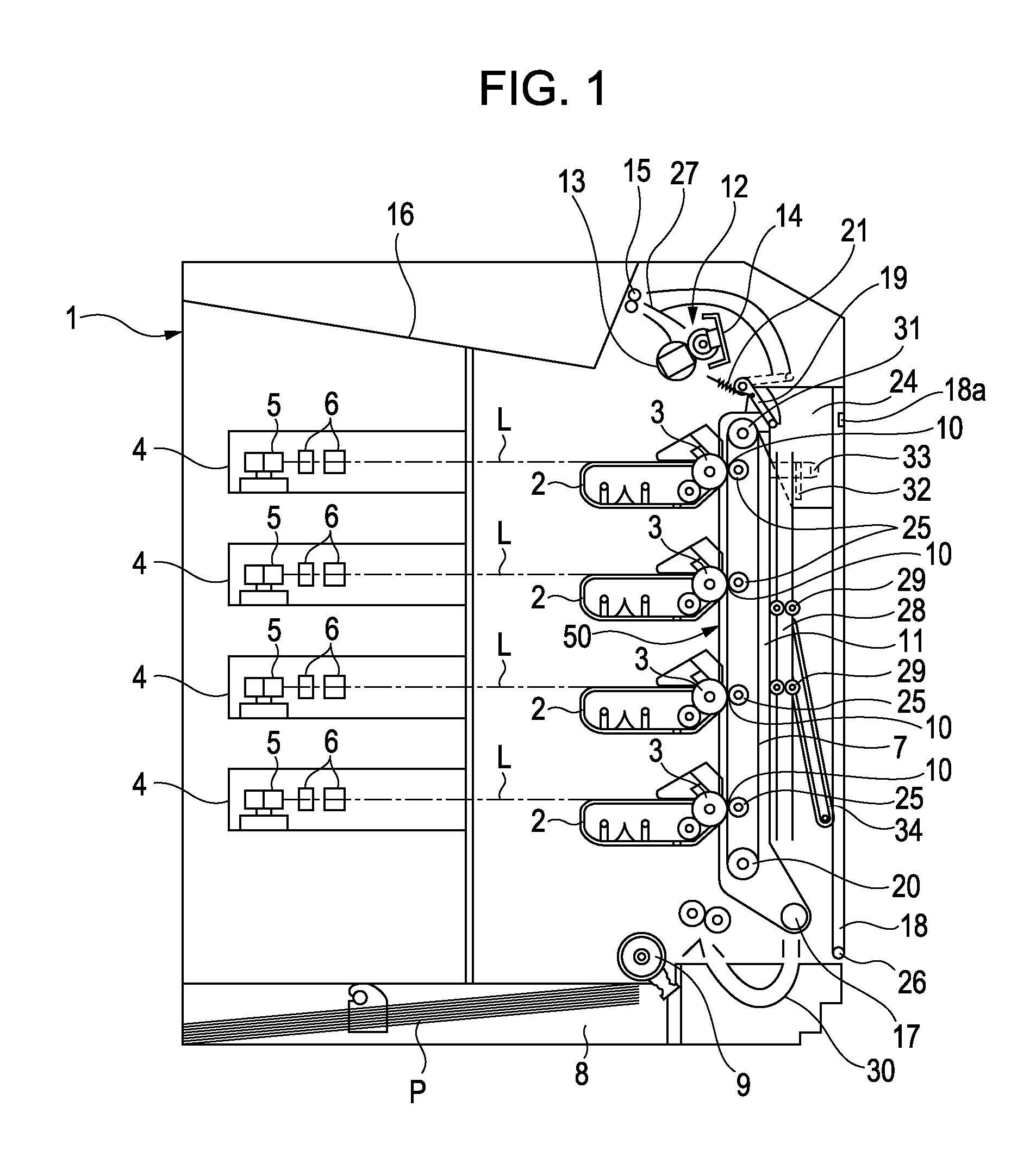
[0023]FIG. 1 is a sectional view of an exemplary image forming apparatus according to an embodiment of the present invention. The image forming apparatus according to the embodiment uses a color transfer electro-photographic process. This is a tandem-type full-color laser beam printer in that process cartridges of yellow (Y), magenta (M), cyan (C), and black (BK) using non-magnetic mono-component toner and arranged in a line.
[0024] An image forming method of the image forming apparatus according to the embodiment will be described below in detail. Process cartridges 2 are detachably arranged in a printer body 1. Each process cartridge 2 according to the embodiment includes a photosensitive drum 3, which is an image bearing member, a charging portion for charging the photosensitive drum 3, a developing unit for developing the image on the photosensitive drum 3, and a cleaning unit for cleaning the residual toner on the photosensitive drum 3. The d...
second exemplary embodiment
[0063] An illustration of an exemplary image-forming apparatus according to a second embodiment is shown in FIG. 7. The image-forming apparatus according to the embodiment, in the same way as in the first embodiment, is a color laser beam printer having four process cartridges using non-magnetic mono-component toner and an electro-photographic process.
[Exemplary Image-forming Apparatus]
[0064] The configuration specific to the present embodiment will be described below. It is noted that like reference characters designate like components common to the first embodiment, and the description of the components with the same structure is omitted.
[0065] In the apparatus according to the embodiment, an intermediate transfer belt 40 is arranged so as to oppose the photosensitive drums 3 of the linearly arranged process cartridges 2. The toner image formed on the photosensitive drums 3 is sequentially transferred on the intermediate transfer belt 40 at primary transfer parts 41 so as to ov...
PUM
 Abstract
Description
Claims
Application Information
 - R&D
- Intellectual Property
- Life Sciences
- Materials
- Tech Scout
- Unparalleled Data Quality
- Higher Quality Content
- 60% Fewer Hallucinations
Browse by: Latest US Patents, China's latest patents, Technical Efficacy Thesaurus, Application Domain, Technology Topic, Popular Technical Reports.
© 2025 PatSnap. All rights reserved.Legal|Privacy policy|Modern Slavery Act Transparency Statement|Sitemap|About US| Contact US: help@patsnap.com