Clamp apparatus

a technology of apparatus and clamping rod, which is applied in the direction of positioning apparatus, metal-working machine components, manufacturing tools, etc., can solve the problems of increasing the number of process steps and man-hours required to carry out such maintenance, and achieves the effect of facilitating and improving maintenance ease, and facilitating the implementation of change in the output of the apparatus

Active Publication Date: 2015-05-28
SMC CORP
View PDF3 Cites 13 Cited by
  • Summary
  • Abstract
  • Description
  • Claims
  • Application Information

AI Technical Summary

Benefits of technology

[0005]Further, in the case one wishes to increase the clamping force applied to the workpiece, it is necessary to prepare a different clamp apparatus having a drive unit that produces a different output, and since it is necessary to secure a large storage space for the different clamp apparatus, a single clamp apparatus has been desired, which enables a change in output of the apparatus to easily be implemented.
[0006]A general object of the present invention is to provide a clamp apparatus which facilitates and improves ease of maintenance, and which enables a change in output of the apparatus to easily be implemented.
[0014]Accordingly, in the case that a maintenance operation such as exchange of the drive unit or the like is to be carried out, since the connection between the driving force transmission mechanism and the drive unit can easily be released by the connection mechanism, for example, in comparison with the conventional clamp apparatus in which a drive unit and a link mechanism (driving force transmission mechanism) are connected by bolts or the like, it is unnecessary to carry out complicated operations such as removal of bolts or the like. Owing thereto, ease of maintenance of the clamp apparatus can be enhanced. Further, by removal of the drive unit from the body and replacement thereof with a different drive unit, a change in the output of the drive unit in the same clamp apparatus can be implemented.

Problems solved by technology

However, in such a case, the piston rod of the drive unit and the link mechanism provided on the side of the body are connected by bolts or the like, and after the connection between such components has been released, the drive unit becomes detached from the body.
Such an operation is difficult to perform and leads to an increase in the number of process steps and man-hours required to carry out such maintenance.

Method used


Image

  • Clamp apparatus
  • Clamp apparatus
  • Clamp apparatus

Examples


first embodiment

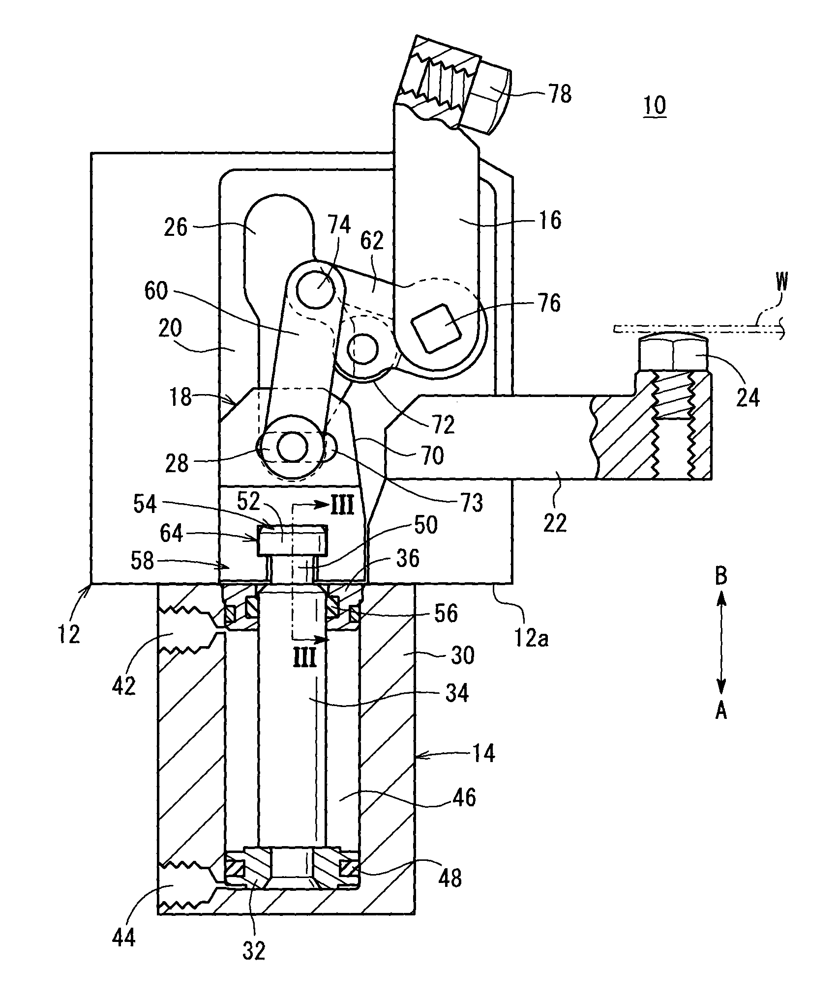
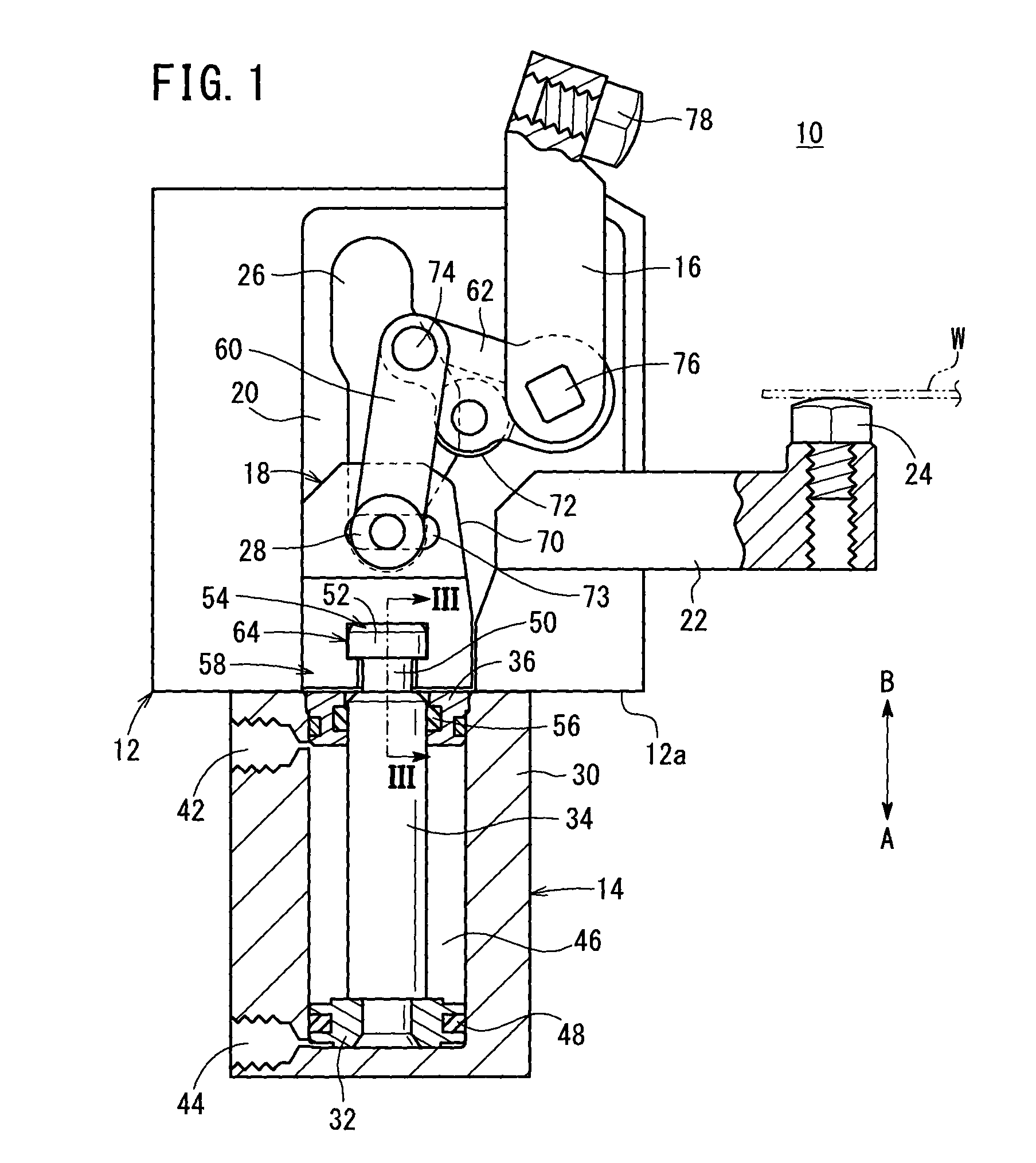
[0047]The clamp apparatus 10 according to the present invention is constructed basically as described above. Next, operations and effects of the clamp apparatus 10 will be described. In the following descriptions, the unclamped state shown in FIG. 1 shall be treated as an initial position.

[0048]In the initial condition, pressure fluid is supplied to the first port 42, and by lowering of the piston 32, via the driving force transmission mechanism 18, the clamp arm 16 is placed in a state of being separated substantially perpendicularly with respect to the support member 22. Further, a thin plate shaped workpiece W is mounted beforehand with respect to the support member 22 of the body 12.

[0049]At first, in the initial position of the clamp apparatus 10 shown in FIG. 1, under a switching operation of a non-illustrating switching device, the pressure fluid which had been supplied to the first port 42 is supplied instead to the second port 44 from the pressure fluid supply source, while...

second embodiment

[0077]In the foregoing manner, with the second embodiment, in the clamp apparatus 100 having the toggle link mechanism 102, the connector 54 of the piston rod 34 constituting the drive unit 14 is connectable with the displaceable body 58 of the driving force transmission mechanism 18 that transmits the driving force of the drive unit 14 to the clamp arm 16. Owing thereto, in the case that a maintenance operation such as exchanging the drive unit 14 or the like is carried out, merely by a simple operation of detaching the piston rod 34 from the displaceable body 58 after the displaceable body 58 has been made to project from the body 12, an operation can be performed easily to remove the drive unit 14. As a result, in comparison with the conventional clamp apparatus in which a drive unit and a link mechanism (driving force transmission mechanism) are connected by bolts or the like, it is unnecessary to carry out complicated operations such as removal of bolts or the like. Owing there...


PUM


Abstract

A clamp apparatus is equipped with a body, and a drive unit having a piston displaced under the supply of a pressure fluid. A clamp arm is disposed rotatably on the body. In addition, a piston rod of the drive unit is connected detachably with respect to a displaceable body of a driving force transmission mechanism which is disposed in the interior of the body. Upon detachment of a connector of the piston rod from a connecting recess of the displaceable body, the state of connection between the drive unit and the driving force transmission mechanism is released.

Description

TECHNICAL FIELD[0001]The present invention relates to a clamp apparatus, which is driven under the supply of a pressure fluid, for clamping a workpiece on an automated assembly line or the like.BACKGROUND ART[0002]Heretofore, in an automated assembly line for automobiles, for example, clamping by a clamping apparatus is carried out, in a state in which pre-formed body panels are overlapped and positioned, and an assembly step is carried out whereby the body panels are welded together.[0003]Such a clamp apparatus, for example, as disclosed in U.S. Pat. No. 4,905,973, is equipped with a body, a drive unit which is made up from a cylinder connected to the body, and a clamp arm that projects externally with respect to the body. In addition, by displacing a piston of the drive unit by supplying air to the cylinder, a piston rod is displaced together with the piston, whereby the clamp arm, which is connected to a link mechanism constituted from a plurality of arms, is rotated through a pr...

Claims


Application Information

Patent Timeline
Patent Type & Authority Applications(United States)
IPC IPC(8): B25B5/12B25B5/16
CPCB25B5/16B25B5/122
Inventor FUKUI, CHIAKITAKAKUWA, YOUJI
Owner SMC CORP
Why Eureka
Try Eureka