Methods and systems for managing facility power and cooling

a technology for managing facilities and power systems, applied in the direction of domestic cooling equipment, lighting and heating equipment, instruments, etc., can solve the problems of putting strain on the cooling and power systems of facilities, and affecting the use of cooling programs

Active Publication Date: 2007-02-15
SCHNEIDER ELECTRIC IT CORP
View PDF55 Cites 314 Cited by
  • Summary
  • Abstract
  • Description
  • Claims
  • Application Information

AI Technical Summary

Benefits of technology

[0035] In the method, the at least one air removal unit may be an in-row cooling unit, and the capture index may be equal to a ratio of captured air to total air exhausted by the at least one equipment rack. The acts may further include determining a capture index for each of the equipment racks. The act of conducting an analysis may include defining a plurality of control volumes, and wherein the method further includes determining airflows in the hot aisle by determining airflow into and out of at least one of the control volumes. The acts may further include comparing the capture index for each of the plurality of equipment enclosures with a threshold. The acts may further include determining a cooling capacity for each of the equipment enclosures based on the capture index for each of the equipment enclosures, and displaying the cool

Problems solved by technology

In modem data centers and network rooms, the increased density of computing equipment used in these facilities has put strains on the cooling and power systems of the facilities.
While existing tools provide a designer with detailed layout information regarding power distribution, these tools typically provide far less help in determining cooling needs for a facility.
Advanced programs that use computational fluid dynamics (CFD) may be used to model the cooling design of a facility, but the use of such programs is extremely limited due to the complexity of the programs, which results in their use being prohibitively expensive and time consuming.
While this system may offer some improvements in speed over a full CFD analysis, it is limited to the use of pre-characterized cells, and does not provide analysis below the cell level.
Programs and systems such as those described above provide idealized results for the cooling performance of a facility and often fail to account for situations which often occur in real life installations, which can dramatically affect the c

Method used


Image

  • Methods and systems for managing facility power and cooling
  • Methods and systems for managing facility power and cooling
  • Methods and systems for managing facility power and cooling

Examples


Embodiment Construction

[0058] This invention is not limited in its application to the details of construction and the arrangement of components set forth in the following description or illustrated in the drawings. The invention is capable of other embodiments and of being practiced or of being carried out in various ways. Also, the phraseology and terminology used herein is for the purpose of description and should not be regarded as limiting. The use of “including,”“comprising,” or “having,”“containing”, “involving”, and variations thereof herein, is meant to encompass the items listed thereafter and equivalents thereof as well as additional items.

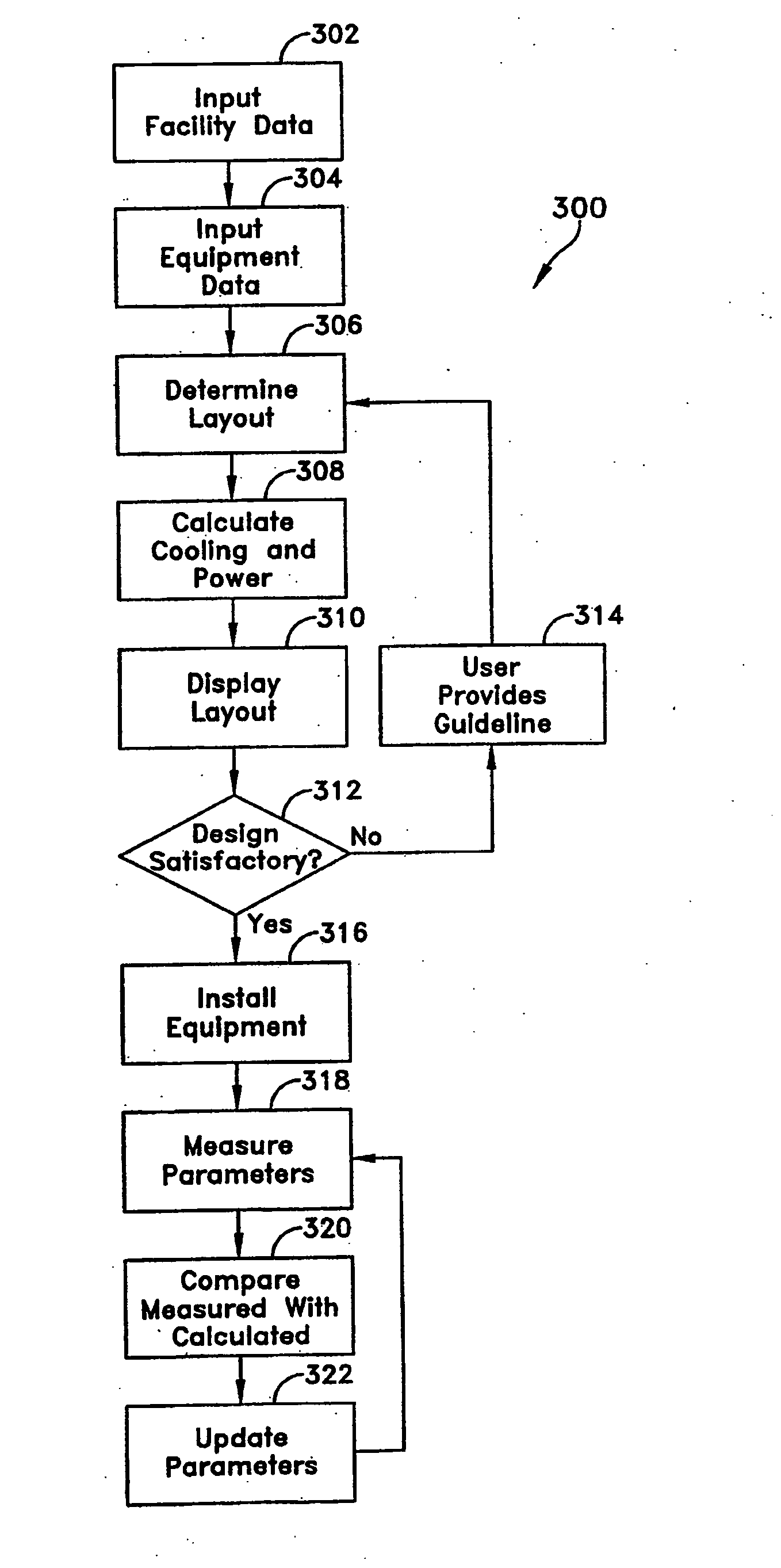
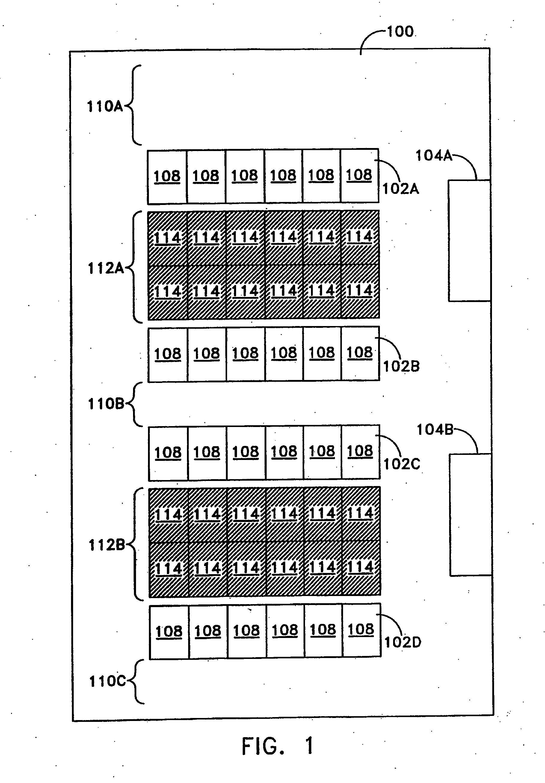
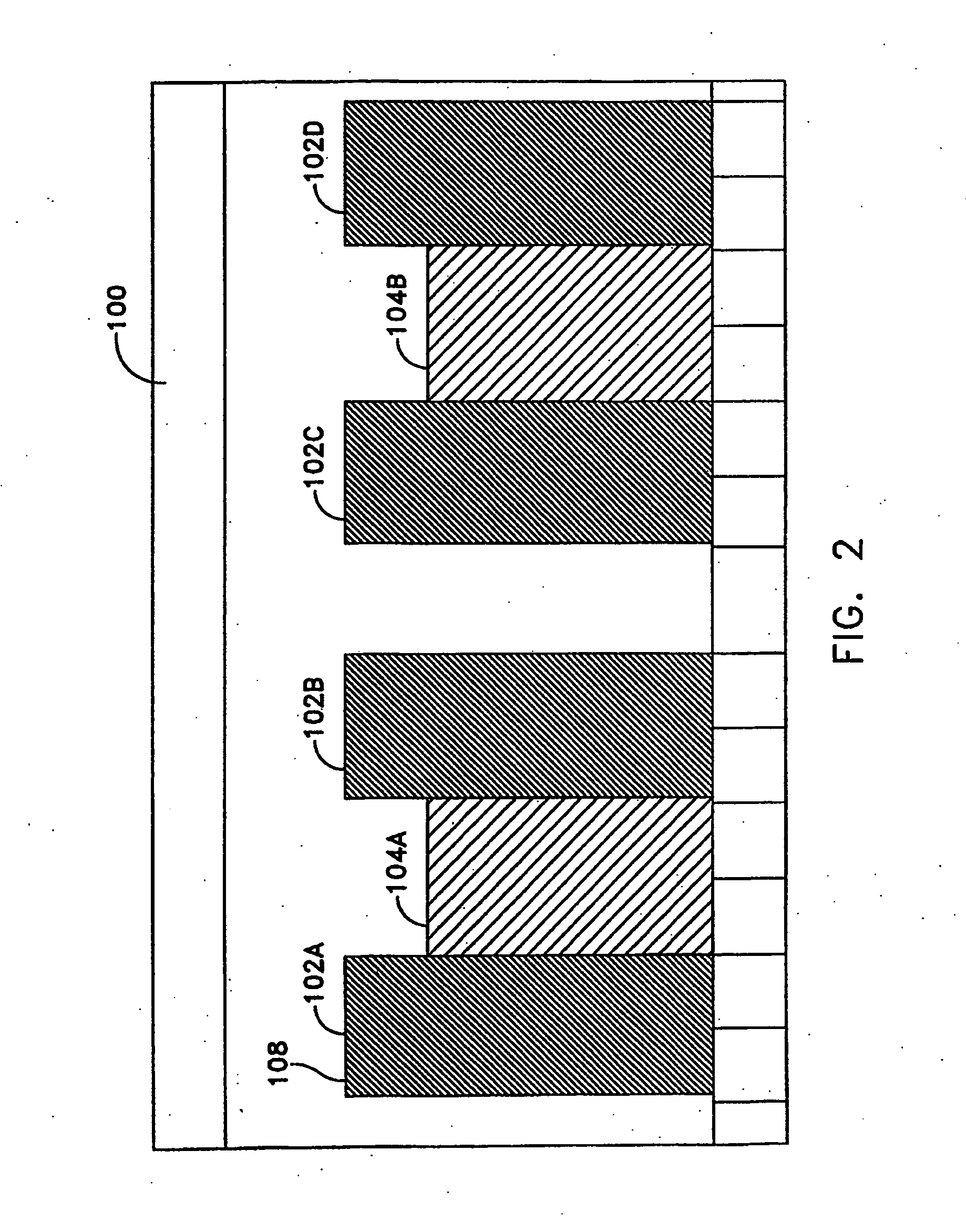
[0059] Embodiments of the present invention may be used to design, manage and retrofit a data center, such as data center 100 which is shown in FIGS. 1 and 2 with FIG. 1 showing a top view of the data center 100, and FIG. 2 showing a side view of the data center 100. As discussed further below, the design of the layout of the data center 100, including power ...


PUM


Abstract

Systems and methods are provided for determining data center cooling and power requirements and for monitoring performance of cooling and power systems in data centers. At least one aspect provides a system and method that enables a data center operator to determine available power and cooling at specific areas and enclosures in a data center to assist in locating new equipment in the data center.

Description

RELATED APPLICATIONS [0001] The present application is a continuation-in-part of U.S. patent application Ser. No. 11 / 120,137 filed May 2, 2005, entitled METHODS AND SYSTEMS FOR MANAGING FACILITY POWER AND COOLING, and the present application claims priority under 35 U.S.C. §119(e) to U.S. Provisional Application Ser. No. 60 / 719,356, filed Sep. 22, 2005, entitled METHODS AND SYSTEMS FOR MANAGING FACILITY POWER AND COOLING, both of which are hereby incorporated herein by reference. Further, this application relates to U.S. patent application Ser. No.______, entitled METHODS AND SYSTEMS FOR MANAGING FACILITY POWER AND COOLING, (Attorney Docket No. A2000-701831) by Rasmussen et al. filed on even date herewith, which is also incorporated herein by reference.BACKGROUND OF INVENTION [0002] 1. Field of Invention [0003] Embodiments of the invention relate generally to methods and systems for managing facility power and cooling. [0004] 2. Discussion of Related Art [0005] Centralized data cent...

Claims


Application Information

Patent Timeline
IPC IPC(8): G06F17/50G05D11/00G05D23/00
CPCG06F1/206G06F2217/80G06F17/5004H05K7/20836G06F30/13G06F2119/08
Inventor RASMUSSEN, NEILVANGILDER, JAMES W,DALGAS, MIKKELBERARD, STEPHENJENSEN, HENRIKDAAE, HENRIKSCHOELLHAMMER, SANDI
Owner SCHNEIDER ELECTRIC IT CORP
Why Eureka
Try Eureka