Manufacturing method of titanium compressor wheel

a compressor wheel and titanium technology, applied in the field of titanium compressor wheel manufacturing, can solve the problems of increased casting, high production cost, and high production cost, and achieve the effects of improving production efficiency, high precision, and improving dimensional accuracy at the time of manufacturing

Inactive Publication Date: 2007-02-22
AIKOKU ALPHA
View PDF3 Cites 29 Cited by
  • Summary
  • Abstract
  • Description
  • Claims
  • Application Information

AI Technical Summary

Benefits of technology

The technical effect of this patent is that it provides a way to make highly precise titanium compressor wheels without having to remove all surfaces during production. This improves the quality of the finished product while also making it easier to correct any balancing issues. Ultimately, this results in more efficient manufacturing with higher yields and lower costs.

Problems solved by technology

The technical problem addressed in this patent relates to improving the manufacturing quality and reliability of titanium compressor wheels used in automobiles. Current methods involve complex processes involving multiple steps including design, mold production, and post-processing, resulting in low yields and poor dynamic balancing. This results in expensive and defective finished parts. There is also a possibility of non-uniformity within the part caused by incomplete removal of pads during the manufacturing process.

Method used


Image

  • Manufacturing method of titanium compressor wheel
  • Manufacturing method of titanium compressor wheel
  • Manufacturing method of titanium compressor wheel

Examples


first embodiment

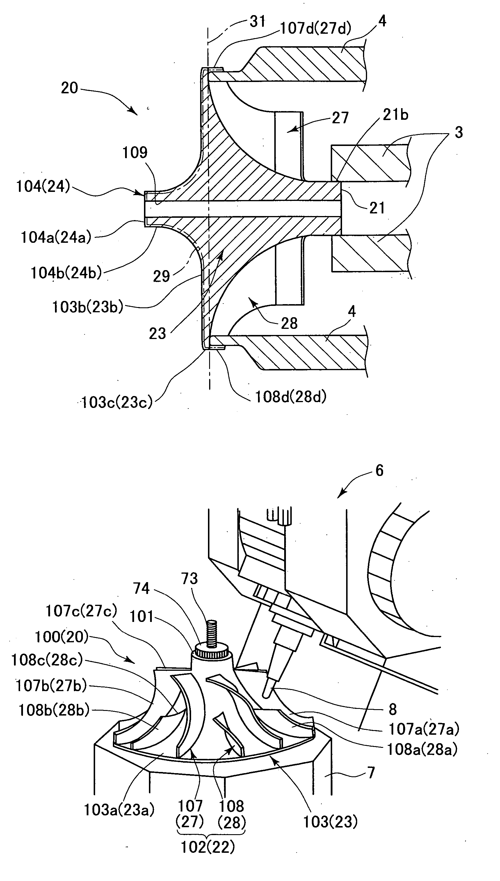
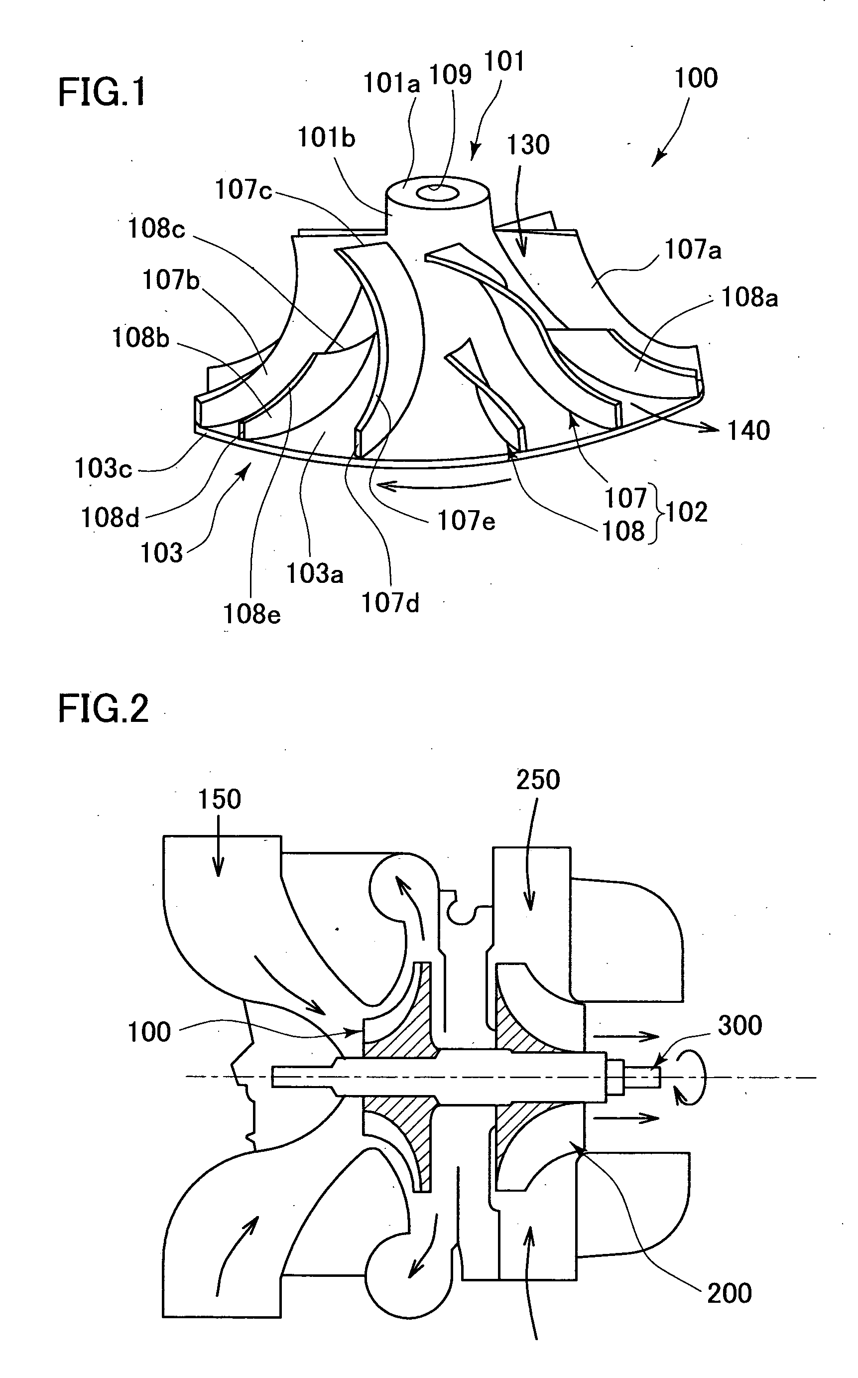
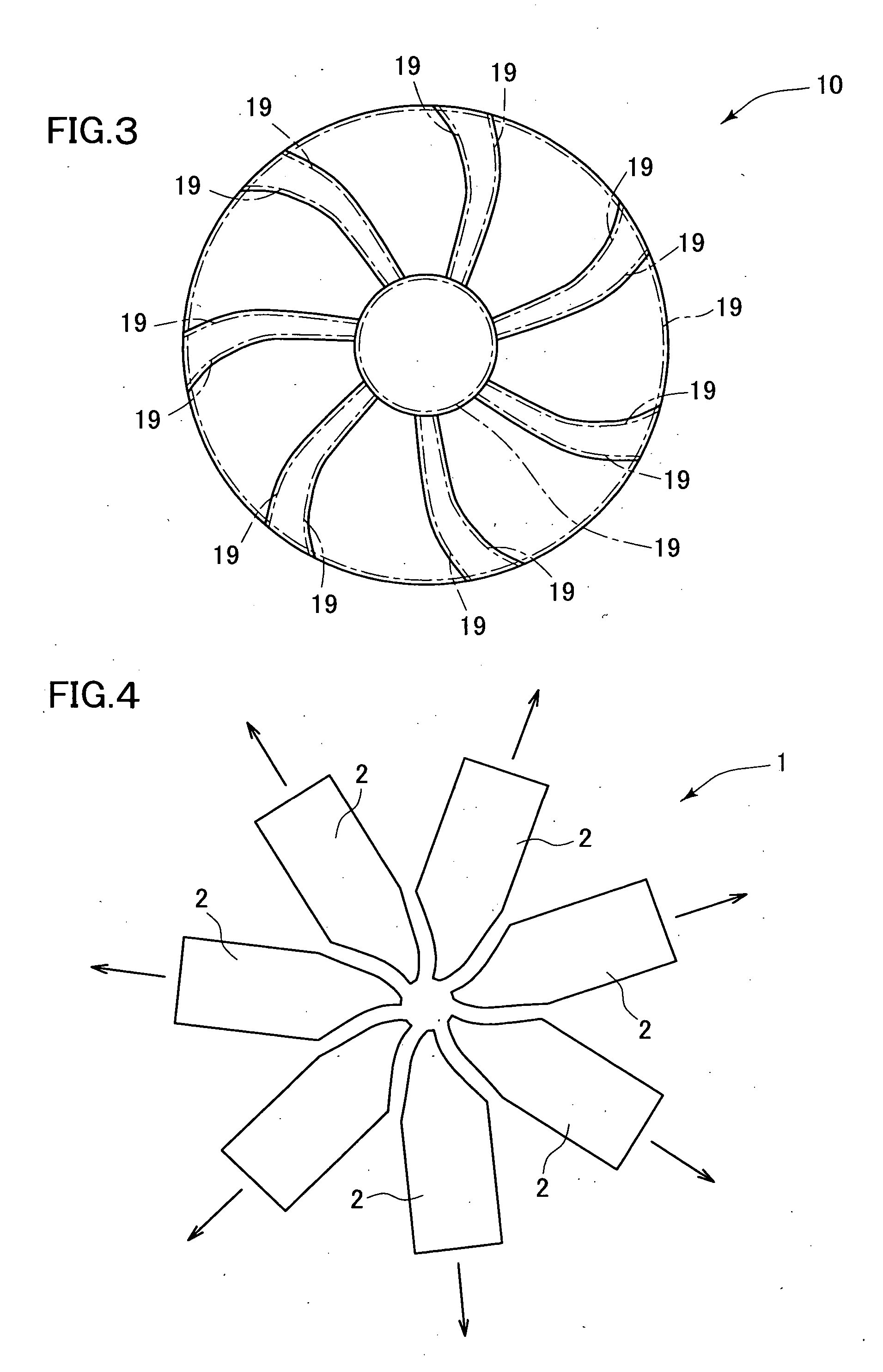
[0056] Next, the manufacturing method of the titanium compressor wheel described in FIGS. 1, 2 will be described with reference to an embodiment of the present invention shown in FIGS. 3 to 14. According to this embodiment, the manufacturing method of the titanium compressor wheel of the present invention includes following three steps. [0057] (1) Positive pattern step (see FIGS. 3, 4) for creating a wax pattern 10 (positive pattern; master pattern; male pattern) to be melted by heat, in which the shape of a compressor wheel 100 is formed to provide entirely an outer face of the compressor wheel (see FIG. 1) with pads 19 having a predetermined thickness as a machining allowance (a removing allowance), by means of a mold 1 so constructed that a plurality of movable insert dies are arranged radiantly such that they are concentrated to a center. [0058] (2) Casting step for creating a cast titanium product 20 to which a wax pattern 10 is transferred according to lost wax casting process...

second embodiment

[0072] Next, another embodiment of the manufacturing method of the titanium compressor wheel described in FIGS. 1, 2 will be explained with reference to FIGS. 15 to 22. According to this embodiment, the manufacturing method of the titanium compressor wheel of the present invention includes following steps: [0073] (1) Positive pattern step for creating a wax pattern 10 (positive pattern; master form; male pattern) provided entirely with pad 19 having a predetermined thickness as a machining allowance (a removing allowance) using a mold 1 comprised of a plurality of movable insert dies 2 (see FIGS. 3, 4, and 15); [0074] (2) Positive pattern machining step (Positive pattern removing step) for creating a cast wax pattern 110 (positive pattern; master form; male pattern) by removing the portions 19 corresponding to the pads of the wax pattern 10 partially by machining processing such as cutting with residual pads 15 left (see FIGS. 16 to 19); [0075] (3) Casting step for creating a cast t...

third embodiment

[0103] Next, still another embodiment of the manufacturing method of the titanium compressor wheel described in FIGS. 1, 2 will be explained with reference to FIGS. 23, 24. According to this embodiment, the manufacturing method of the titanium compressor wheel of the present invention includes following three steps: [0104] (1) Wax pattern 10 (positive pattern; master form; male pattern) provided entirely with the pads 19 having a predetermined thickness as a machining allowance (a removing allowance) by the mold 1 constituting of a plurality of movable insert dies 2 (see FIGS. 3, 4, and 15); [0105] (2) Positive pattern machining (Positive pattern removing) step for creating a complete wax pattern 130 (final complete configuration positive pattern; master form; male pattern) of substantial final complete configuration by removing the portions 19 corresponding to the pads of the wax pattern 10 by cutting or the like (see FIGS. 16 to 19, 23); and [0106] (3) Casting step for creating a ...


PUM

PropertyMeasurementUnit
Thicknessaaaaaaaaaa
Diameteraaaaaaaaaa

Abstract

The present invention provides a manufacturing method of high precision titanium compressor wheel in which by removing pads attached on an entire surface entirely as a machining allowance in manufacturing process, dimensional accuracy at the time of manufacturing is intensified, and correction work of dynamic balance (rotation balance) is simplified or omitted so as to improve yield of products and suppress boosting of manufacturing cost. The outer peripheral face of a front cast boss portion of a cast titanium product is fixed with a chuck of lathe. A plurality of receiving plates projecting from the lathe are positioned between respective cast blades and front ends thereof are pressed against a disc-like large-diameter front end face formed on a rear half portion of a cast core portion. With a large-diameter front end face of the cast core portion and the outer peripheral face of the front cast boss portion as reference plane, the cast titanium product is held by the chuck and receiving plates and rotated. By turning the end face and outer peripheral face of a rear cast boss portion, the rear face and outer peripheral face of the cast core portion and trailing edges of cast full blades and cast splitter blades, portions corresponding to the pads at these portions are removed from the cast titanium product.

Description


Claims


Application Information

Patent Timeline
Owner AIKOKU ALPHA
Why Eureka
Try Eureka