Stator arrangement for an electric machine and a method for manufacturing the stator arrangement

Inactive Publication Date: 2007-02-22
MINEBEA CO LTD
View PDF6 Cites 32 Cited by
  • Summary
  • Abstract
  • Description
  • Claims
  • Application Information

AI Technical Summary

Benefits of technology

[0014] When the stator end lamination has essentially the same shape as the remaining stator laminations, in a further embodiment of the invention, projections are formed at the stator end lamination in the area of the pole shoes at the distal ends of the stator teeth, the projections extending in axial direction from the outer face of the stator end lamination. For forming these projections, the stat

Problems solved by technology

One of the problems arising for miniaturized spindle motors is that due to the low permissible overall height of the motor, both the winding space and the space available for the winding terminal is restricted.
In the Japanese publication di

Method used


Image

  • Stator arrangement for an electric machine and a method for manufacturing the stator arrangement
  • Stator arrangement for an electric machine and a method for manufacturing the stator arrangement
  • Stator arrangement for an electric machine and a method for manufacturing the stator arrangement

Examples


Embodiment Construction

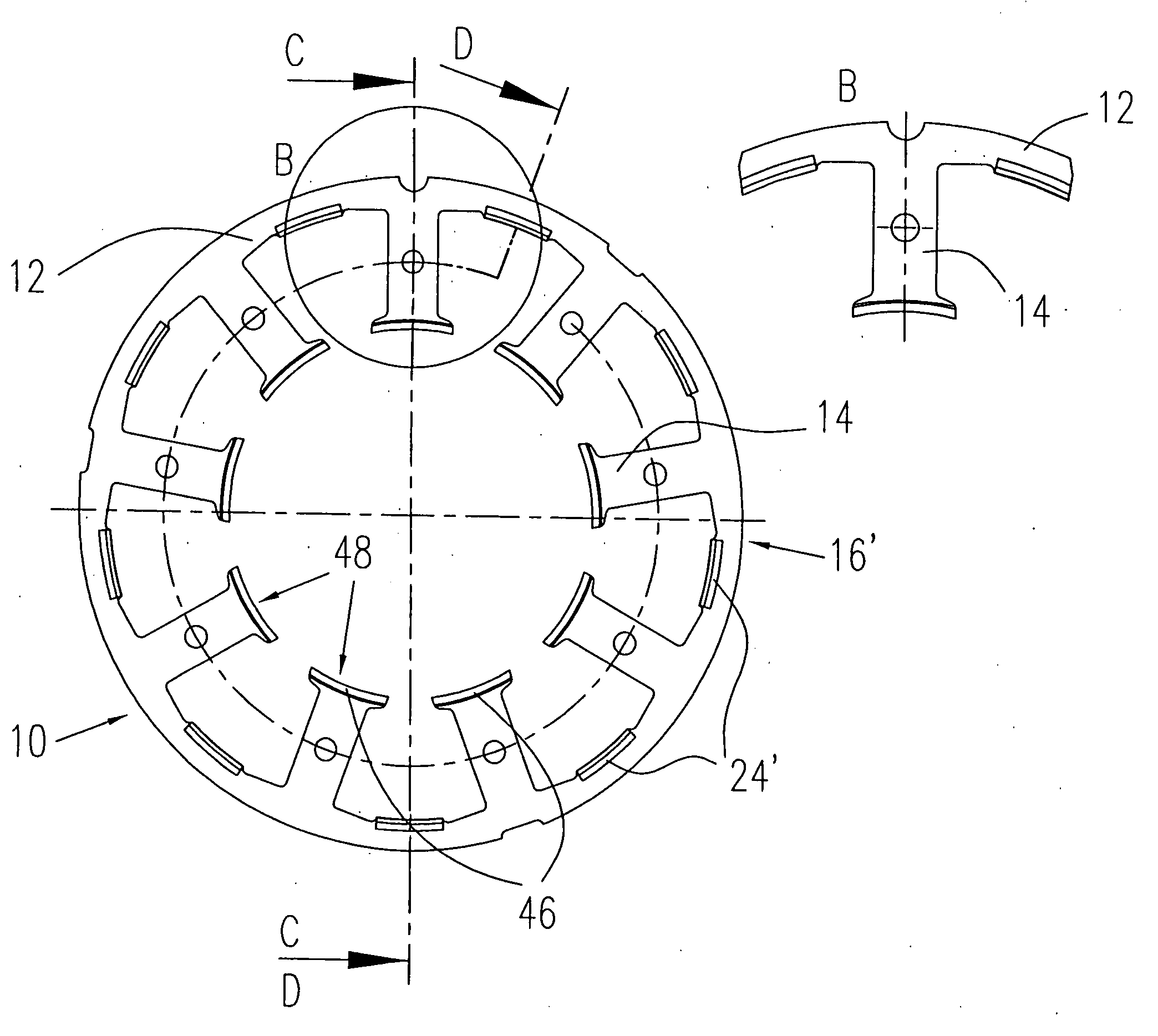
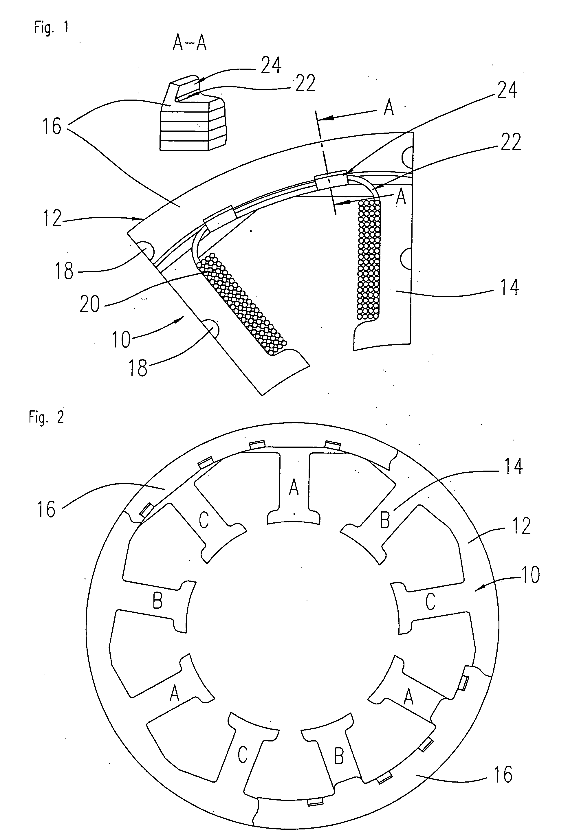
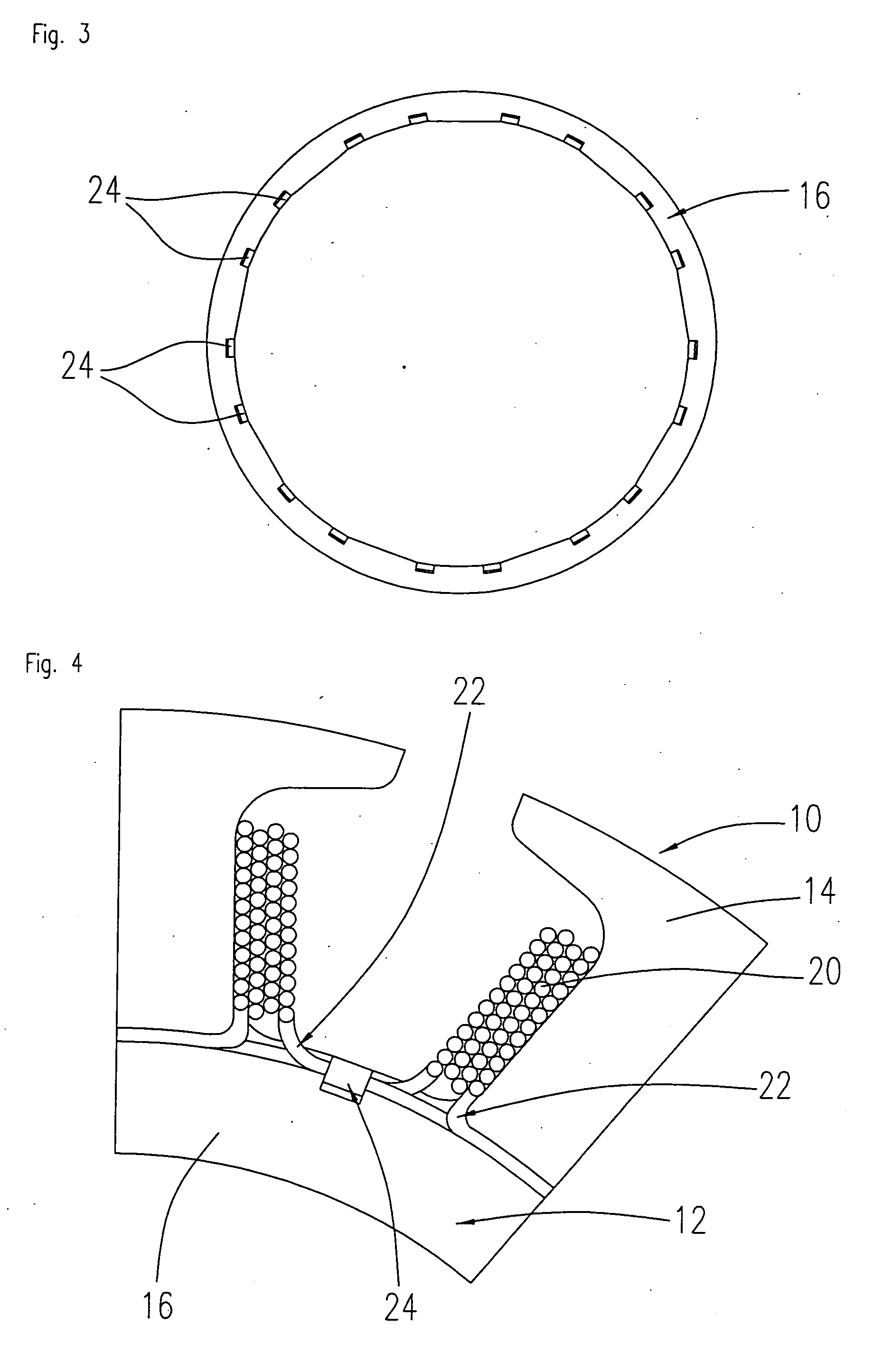
[0025]FIG. 1 schematically shows a partial view of a stator arrangement for an inner rotor motor according to one embodiment of the invention as seen from above. The stator arrangement comprises a stator body 10 that has a back yoke ring 12 and stator teeth 14 projecting radially inwards from the back yoke ring 12. In the section of FIG. 1 indicated by A-A, a sectional view through the stator body 10 along the line A-A is shown in perspective. It can be seen from this that the stator body 10 is made up of a stack of stamped and packed metal laminations. At least the uppermost of these laminations is designed as an additional ferromagnetic lamination ring 16, the so-called stator end lamination, that is preferably made of the same material as the other laminations in the stack but does not have any stator teeth 14. The laminations making up the stator body 10 are preferably punched out of thin dynamo sheet metal and connected together using a well-known stamping / stacking process. The...


PUM


Abstract

A stator arrangement for an electric machine having a stator body which has a back yoke ring and a number of stator teeth that project in a radial direction from the back yoke ring, wherein at least one additional ferromagnetic stator end lamination is mounted on at least one end face of the back yoke ring, the additional ferromagnetic stator end lamination being substantially flush with the back yoke ring, wherein projections are formed at the inner or outer circumference of the additional stator end lamination, the projections projecting axially from the outer end face of the stator end lamination and forming a guide for the winding wire.

Description

FIELD OF THE INVENTION [0001] The invention relates to a stator arrangement for an electric machine as well as a method for its manufacture. The stator arrangement comprises a stator body that has a back yoke ring and a number of stator teeth which project from the back yoke ring in a radial direction. BACKGROUND OF THE INVENTION [0002] A preferred field of application for the invention is in brushless DC motors and other permanent magnet motors that can be configured as inner rotor motors or as outer rotor motors. However, the invention can also be applied to other types of electric machines. Electric machines having an inner rotor configuration comprise a rotor arrangement that is mounted onto a shaft and carries one or more permanent magnets, as well as a stator arrangement usually constructed from a number of stacked metal laminations which form a closed stator back yoke from which stator teeth project radially inwards. The stator teeth carry the phase windings. Building up the ...

Claims


Application Information

Patent Timeline
IPC IPC(8): H02K1/00H02K3/00
CPCH02K3/522H02K2203/06
Inventor GU, CHUNHUI
Owner MINEBEA CO LTD
Why Eureka
Try Eureka