Method for transmitting messages in a network

a network and message technology, applied in the field of network transmission methods, can solve the problems of virtually impossible for the sender to determine whether one of the intended recipients is the recipient of the message to be transmitted, difficult to determine whether one of the recipients is the recipient, and the time needed for processing messages is substantially reduced, so as to save staff costs and reduce the effect of data traffi

Inactive Publication Date: 2007-02-22
UNIFY GMBH & CO KG
View PDF13 Cites 2 Cited by
  • Summary
  • Abstract
  • Description
  • Claims
  • Application Information

AI Technical Summary

Benefits of technology

[0012] This method enables data traffic to be substantially reduced. In addition, it cuts the time needed for processing messages, leading to savings in staff costs. Furthermore, the memory requirement—particularly for the recipient—is greatly reduced, and the costs of providing and maintaining the network can also be reduced since backup systems as well as any bandwidths, for example, can be scaled down as a result of the reduction in data traffic.
[0013] Depending on the method selected, it is advantageous if the data concerning the entry of messages at the address data terminal is stored in the address data terminal and / or in the first mail-processing device or at the address data terminal and / or in the first and / or the second mail-processing device. The data concerning the entry of messages in the address data terminal may thus be stored on one or more devices taking into account the prevailing parameters, such as—for example—the network architecture. A further advantage of storage in multiple locations is that it can sometimes eliminate the need to make a further backup, whether on a tape device or similar.
[0014] In a preferred embodiment the data concerning the entry of messages at the address data terminal is stored in the mail-processing device in which the identifier is evaluated. This eliminates the need for information for the evaluation process in the mail-processing device to be retrieved via the network, ensuring high evaluation speed. It is preferable for the first mail-processing device to be implemented in the sender data terminal and / or for the second mail-processing device to be implemented in the address data terminal. This embodiment is characterized in that no additional hardware needs to be provided in the network for the inventive method.

Problems solved by technology

Whilst such a message would once have needed to be painstakingly copied or passed on from one recipient to the next—a time-consuming process—it is now possible for the message to be copied to them by electronic means in a matter of seconds.
For the sender of a message, finding out which persons belong to a message group is a highly time-consuming or even impossible task.
It is therefore also difficult to determine whether one recipient of the message to be transmitted has already received it as a member of a different message group.
It is virtually impossible for the sender to determine whether one of the intended recipients has already received the message from another sender.
This is particularly problematic in the case of messages that have been or are to be forwarded.
However, because there is a multitude of message group distribution lists in existence, it is virtually impossible for the manager to tell that one of his employees has already received the information via a different route.
As a result of the employee receiving the message more than once, the amount of data traffic in the network is unnecessarily increased as well as the productivity of the employee being reduced since the latter has to spend part of his working time on identifying and deleting duplicate messages that have been received.
In addition, when deleting such a duplicate message, it is often not sufficient simply to delete the message without opening it since it is not usually possible to tell from the subject line whether or not the sender of the message has added a comment to it.

Method used


Image

  • Method for transmitting messages in a network
  • Method for transmitting messages in a network
  • Method for transmitting messages in a network

Examples


Embodiment Construction

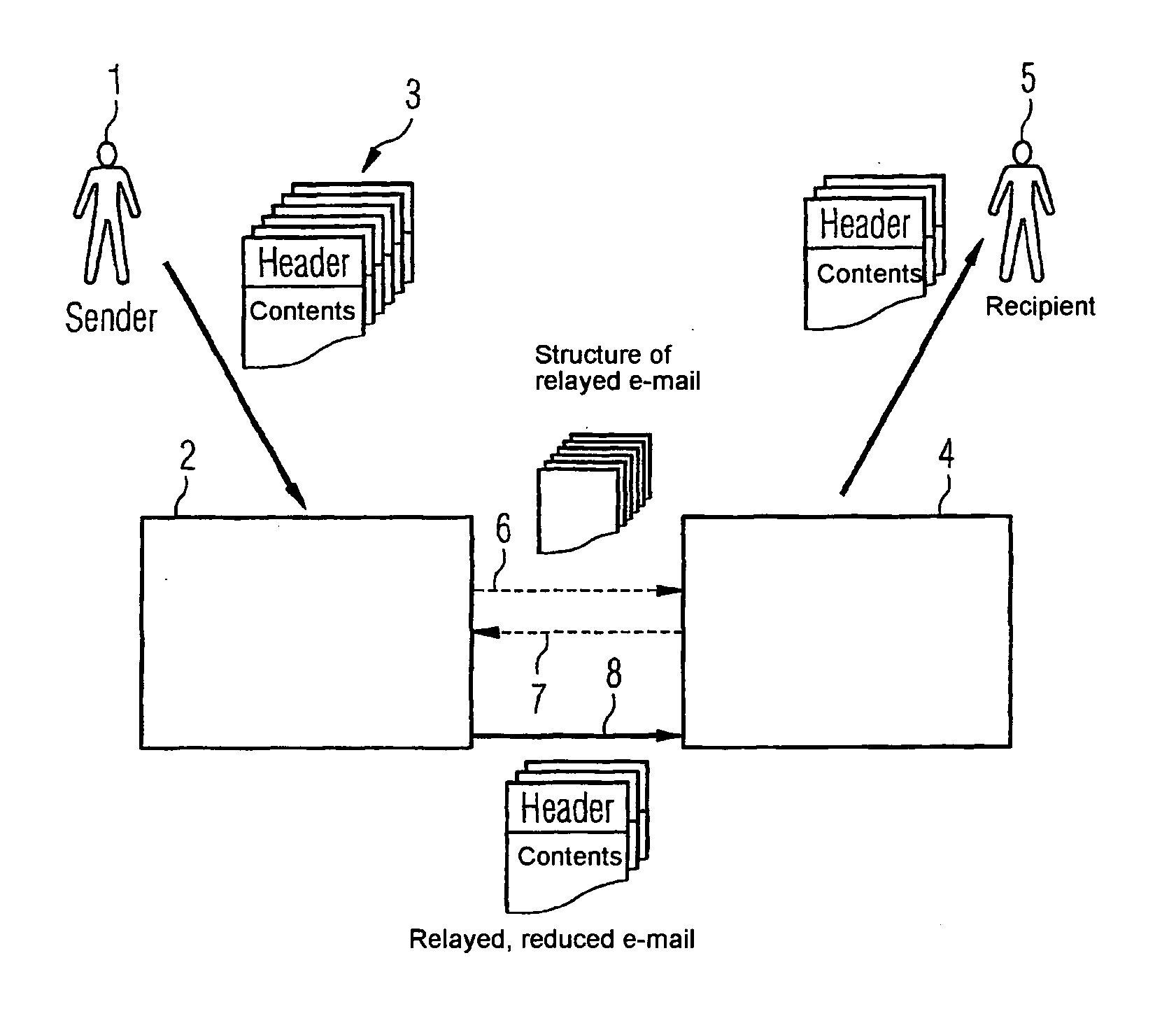
[0026]FIG. 1 schematically illustrates the components involved in the method for transmitting messages. These are as follows: a sender 1, a mail processing device 2 assigned to the sender 1, a message 3 which consists of message elements, i.e. a header and attachments, a mail processing device 4 assigned to the recipient, and a recipient 5 for the message.

[0027] The following data is assigned to the message 3: an identifier to indicate that it is a relayed message; date and time of transmission, and an e-mail address of the sender. Special additional information is assigned to each message element when the message 3 is forwarded. These are: date and time of creation of the original message, where these differ from the time of transmission, an e-mail address of the original sender, where this differs from the e-mail address of the sender 1, and the contents of the message element.

[0028] The sequence of a message relaying process is described in greater detail below on the basis of ...


PUM


Abstract

The invention relates to a method for transmitting messages in a network via data terminals connected thereto. This method comprises the following steps: sending a message to be relayed from a sender data terminal to an assigned first mail processing device assigning a unique identifier to the message which indicates that a message to be relayed is in the sender data terminal or in the first mail processing device; evaluating the identifier by the first mail processing device based on data present therein concerning the entry of a message at an address data terminal from the past, and in response to the evaluation result, transmitting in a triggered or blocked manner the message or parts thereof to the address data terminal. The invention also relates to a data terminal and network that carry out the inventive method using mail processing devices.

Description

CROSS REFERENCE TO RELATED APPLICATIONS [0001] This application is the US National Stage of International Application No. PCT / EP2004 / 051695, filed Aug. 3, 2004 and claims the benefit thereof. The International Application claims the benefits of German application No. 10345542.6 DE filed Sep. 30, 2003, both of the applications are incorporated by reference herein in their entirety.FIELD OF THE INVENTION [0002] The invention relates to a method for transmitting messages in a network according to the claims, a data terminal according to the claims, and a network for transmitting data according to the claims. BACKGROUND OF THE INVENTION [0003] The transmission of electronic information by electronic means, i.e. by e-mail for instance, is becoming increasingly important in the current age of modern information technology. As well as reducing costs, for example because less paper is used or because of savings in postage and delivery costs, which may be extremely high especially where spee...

Claims


Application Information

Patent Timeline
Patent Type & Authority Applications(United States)
IPC IPC(8): H04L12/66H04L12/58
CPCH04L12/585H04L51/12H04L12/5885H04L51/234H04L51/212
Inventor UECKER, RAINER
Owner UNIFY GMBH & CO KG
Why Eureka
Try Eureka